¶ ENG-411 2023 study report
CARINA - Deploying a constellation of Lunar Pathfinders around the Moon
¶ Report Status
Version: I01
Reviewed by: David Rodríguez
Review date: 22/05/2023
Review status: ✅DONE
The collection of data for future lunar exploration and scientific research requires the launch of constellations of satellites around the Moon. This study focuses on the design of a deployer for a lunar satellite constellation comprising nine lunar pathfinder satellites, to be launched into two different frozen orbits around the Moon with the help of the European Launcher Ariane 64 (A64). The area of interest is the south pole of the Moon, which is considered as a prominent destination for future exploration missions due to the presence of water ice embedded within the regolith. To meet customer needs and maximize the number of satellites sent, eight subsystems including thermal, power, CDHS, AOCS, configuration, structure and mechanism, trajectory analysis, and propulsion, worked together with systems engineers to satisfy various constraints and requirements. The team's efforts resulted in the early development of a reliable and efficient deployer capable of accurately deploying the lunar pathfinder satellites in their designated orbits, thereby enhancing lunar communication and navigation capabilities. This study represents a valuable contribution to the field of lunar exploration and scientific research, demonstrating the effectiveness of concurrent design techniques and interdisciplinary teamwork in space mission planning and execution.
The following contains all the relevant information resulting from this study, from the context and mission objectives to lessons learned.
For a list of terms and acronyms often used, check the Glossary section.
This study was performed at eSpace’s Concurrent Design Facility by the following team:
| Name | Affiliation | Role |
|---|---|---|
| L’Emira Emma Chehab | EPFL | System Engineering |
| Quentin Delfosse | EPFL | System Engineering |
| Arion Zimmermann | EPFL | Attitude & Orbit Control (AOCS) |
| Lionel Isoz | EPFL | Communications & Data Handling (CDHS) |
| Nathan Soury-Lavergne | EPFL | Configuration |
| Lucile Siegfried | EPFL | Power |
| Oliver Pineda Suárez | EPFL | Power |
| Valentin Suppa Gallezot | EPFL | Propulsion |
| Kent Barbey | EPFL | Propulsion |
| Lina Kuhlmann | EPFL | Structures & Mechanisms |
| William Cottier | EPFL | Structures & Mechanisms |
| Valentin Moret | EPFL | Thermal |
| Jonathan Wei | EPFL | Trajectory Analysis |
| Théo Pugin-Bron | EPFL | Trajectory Analysis |
Under the responsibility of:
M. Udriot, eSpace, Study Coordinator
D. Rodríguez, eSpace, Study Coordinator
With the technical support of:
S. Hamel, eSpace, Systems Engineering Support
A. Saada, eSpace, Systems Engineering Support
C. Norhadian, eSpace, Logistics & Admin Support
¶ Introduction
¶ Background
Between March 20th and 31st, 2023, a group of 14 EPFL students from various disciplines participated in the ENG-411 Concurrent Engineering of Space Missions course, a two-week program organized by eSpace. The course aimed at teaching students the principles of concurrent design for space missions, while encouraging the development of a new concurrent design facility (CDF). The program provided an interdisciplinary learning environment where students collaborated to design and develop space mission concepts, organizing their knowledge and expertise in a structured way.
¶ Objective
The main objective of this study is to design and develop a deployer that can transport and deploy a constellation of satellites into frozen orbits around the Moon.
¶ Scope
The scope of the mission/system design will encompass various critical aspects, including the selection of an appropriate European launcher, deployer design, and mission planning and execution. The primary objective is to develop a deployer that can effectively deploy a maximum number of satellites into orbits around the Moon, enhancing lunar communication and navigation capabilities. The satellites shall be considered as inputsto the study, and only the deployer will need to be designed to meet the specific requirements of the mission, including accurate and reliable deployment of the satellites in the desired orbits.
¶ Executive Summary
A lunar mission will be launched from Kourou using the Ariane 64 rocket (A64), carrying a deployer with a Trans Lunar Injection (TLI) system to place it into an elliptical orbit. The deployer will then deploy nine satellites separately to achieve optimal coverage of the lunar surface. A total delta-v of 1,578.4 m/s and 3,587 kg of propellant will be required. The customer’s mission will provide precise navigation, redundancy, and extended coverage of the south pole of the Moon.
¶ Study Objectives
The study objectives for the Carina mission is to deploy a satellite constellation around elliptical orbits around the Moon with the highest possible coverage at the south pole of the Moon. Water ice has been suspected to exist in lower temperature regions of the lunar poles since the 1960s, where it is protected from sunlight in shadowy "cold traps.” Recent missions by LCROSS) and LRO) have confirmed the presence of water ice in the lunar south pole, making it a key destination for future exploration missions. Water is a valuable resource in space, with numerous practical applications such as propellant production and radiation shielding. Additionally, water ice can provide valuable scientific information about the history and chemistry of the Solar System.
¶ Requirements
The mission requirements and main system requirements, as provided by the engineering team at eSpace prior to the study and completed by the design team, are presented in the following table.
| Ref | Requirement |
|---|---|
| MIS.001 | The deployer shall transport Lunar Pathfinder satellite(s) to lunar orbit |
| MIS.002 | No debris shall be left on Earth orbit protected regions, on the lunar surface or on constellation operational orbits during any phase of the mission. No debris should be left on lunar orbit or translunar/cislunar trajectories, during any phase of the mission |
| MIS.003 | The deployer shall use a european launcher to reach Earth orbit |
| MIS.004 | The deployer shall maximize the number of satellites transported |
| MIS.005 | The mission duration shall be optimized for a fast deployment of lunar navigation services |
| CTN.001 | A preliminary cost estimation of the proposed mission should be approximated using the launch costs as main driver only |
| SYS.FUN.001 | The deployer shall accommodate satellites of the constellation during all phases of the mission until deployment |
| SYS.FUN.002 | The deployer shall allow the safe deployment of all satellites of the constellation on predetermined elliptical lunar frozen orbits |
| SYS.FUN.003 | The deployer shall allow the safe deployment of all satellites of the constellation on predetermined elliptical lunar frozen orbits |
| SYS.FUN.004 | The deployer shall provide a way of managing its end of life |
| SYS.FUN.005 | The deployer shall provide telemetry to Earth ground stations, allowing to assess its state and status of the mission during each phase |
| SYS.DES.001 | Each function of the deployer shall be commendable from Earth ground stations during each powered phase of the mission. It includes Propulsion and ADCS functions |
| SYS.DES.002 | The deployer design shall be compatible with the selected design of the constellation satellites |
| EPS.FUN.001 | The deployer design shall be compatible with the selected launcher |
| EPS.FUN.002 | The deployer shall survive all environments encountered during the mission, including launch |
| EPS.FUN.002.1 | The Deployer shall autonomously manage its own electrical power |
| EPS.FUN.003 | The Deployer shall have the capacity to store enough power to successfully execute each mission phase |
| EPS.FUN.004 | The Deployer design shall NOT include the use of Radioisotope Thermoelectric Generators |
| PROP.FUN.001 | The Deployer shall have enough propulsion capacity to perform all necessary DV for orbital maneuver during the mission |
| PROP.FUN.002 | The PROP system shall be commandable by ground during each powered phases of the mission |
| PROP.DES.001 | In case of a chemical propulsion system, Hydrazine or Nuclear Propulsion shall not be used |
| TH.FUN.001 | The Deployer(s) shall autonomously manage its own thermal balance |
| TH.FUN.002 | The Deployer(s) shall autonomously manage the payloads thermal balance during all phases before deployment |
¶ Design drivers
To complete this set of requirements, some insights are provided regarding the Pathfinder satellites to be transported to the Moon.
- Pathfinder dimensions: height : 2.5m, length : 1.5 m, width : 1.5 m
- Pathfinder wet mass: 330 kg
- Pathfinder frozen orbits
As any launcher comes with mass and volume constraints, the design of our deployer highly depends on the number of satellites to carry. This number was therefore used as the main design driver of our mission.
¶ Mission/System Design
A summary of the outcome of the study is presented in this section.
During the design of a mission, different modes and phases are considered to ensure the deployer's successful operation. These phases are the different stages of the mission that the deployer will encounter during its mission. Then, the mission architecture is divided into 5 phases: Launch and Early Operation (LEO), Commissioning, Lunar Orbit Insertion (LOI), Operations, and End of Life (EOL). Each phase is further subdivided into different subsystems, including Launch, TLI, Separation with (A64), Commissioning, Insertion, Change of Inclination, Deployment of 5 satellites, Change of (RAAN) of 5°, Deployment of 4 satellites, and Passivation.
This overview outlines the five phases of the lunar mission, along with the timeline until the end-of-life phase :
- LEO
- Launch
- TLI
- Separation with (A64](/glossary#a)) - Commissioning
- Insertion
- LOI
- Change of inclination - Operations
- Deployment of 5 satellites
- Change of (RAAN of 5°
- Deployment of 4 satellites - EOL
To correspond with each phase and subsystem, specific modes have been developed such as Commissioning, Deployment, Idle, Launch, Maneuvering, Nominal_Eclipse, Nominal_Sunlight, and Safe. By considering these different processes during the design phase, one can ensure that the deployer is designed and equipped to handle the various conditions it will encounter during its mission, and that it can perform its intended tasks successfully.
The following figure illustrates the overall concept of operations (CONOPS) for the mission, Carina, a constellation with nine stars.
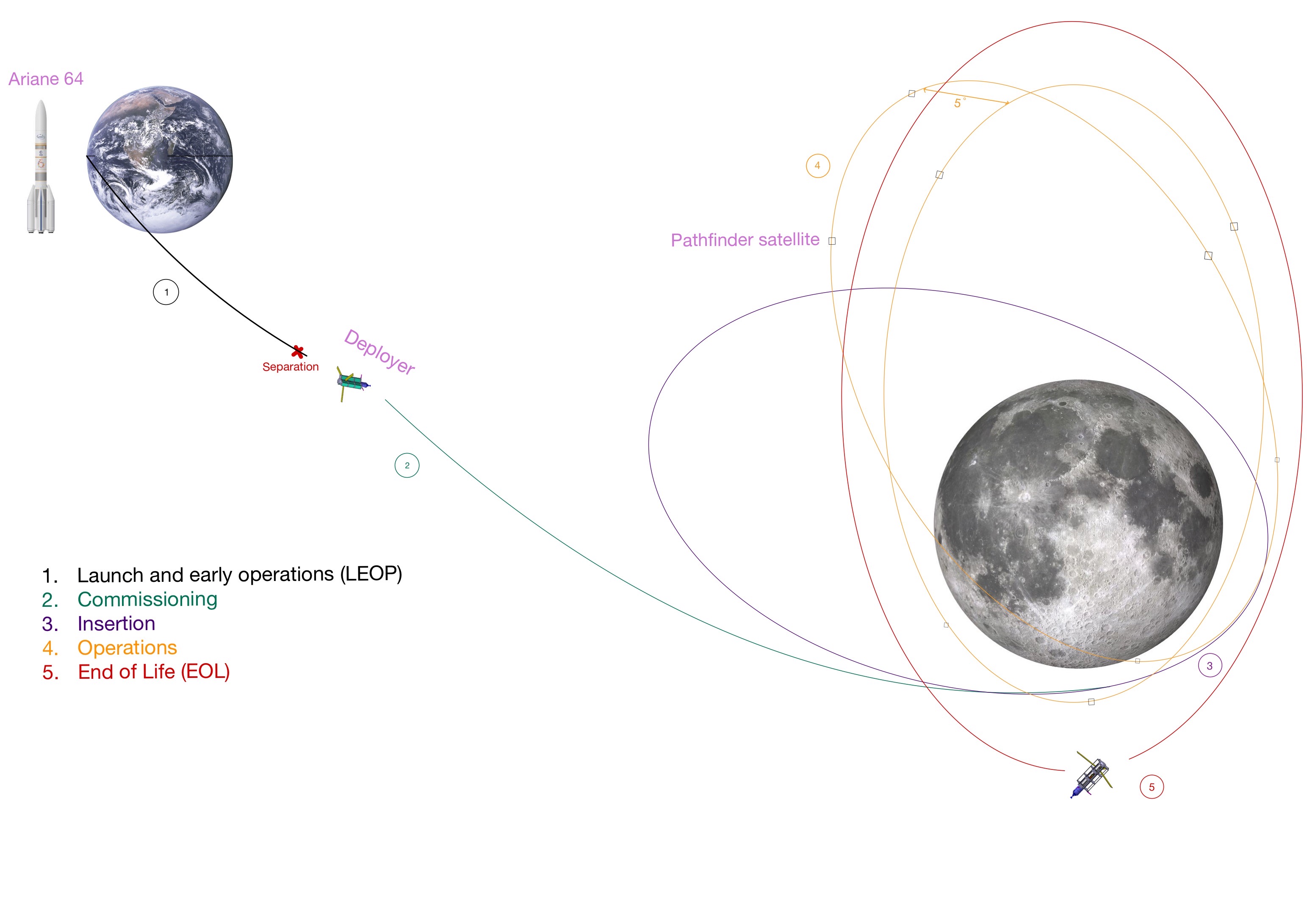
The lunar mission is initiated from Kourou using the A64 rocket, selected based on the requirements of having an European Launcher and for its high payload capacity of 8600 kg with adapter.
The rocket and its TLI system brings the deployer into a 5.4-day trajectory towards the Moon. The TLI system, as specified in the A64 user manual, places the deployer into a highly elliptical orbit with an apogee of 400,000 km and a perigee of 250 km. Once on this orbit, the A64 separates from the deployer, which then performs a LOI burn to enter a new elliptical orbit with a periapsis of 673 km and an apoapsis of 7331 km. A subsequent burn aligns the deployer's orbit at a 54.8° angle to the Moon's equator, which corresponds to a stable orbit known as a frozen orbit.
The deployer then deploys five satellites separately, each at a different time. To ensure optimal coverage of the lunar surface, the deployer changes the RAAN of 5°, creating two distinct orbital planes for the satellites. The natural RAAN drift is too slow for the short mission timeline, which must be kept under 26.4 days to prevent propellant vaporization issues. After the deployment of the final four satellites, the deployer enters the end-of-life phase in higher orbits. The choice of having nine lunar pathfinder satellites provides precise navigation, redundancy, and extended coverage of the south pole of the Moon.
In numbers, here are the final overall details of the Carina mission:
- Total delta-v required for all the maneuvers : 1’578.4 m/s
- Total propellant mass : 3’587 kg
- Overall wet mass of the deployer (without A64 adapter) : 8465.78 kg
- A64 adapter mass : 100 kg
- Power : 3’065.67 W
Further details on the mission and the design of each subsystem are presented in the following results section.
¶ Results
Each subsystem translated the high-level requirements described previously into lower-level, more precise requirements that were applicable to their respective design and operations. In this report, the subsystem requirements are presented and the final solutions that were developed throughout several iterative loops. The final solutions were selected based on their ability to meet the requirements while ensuring the reliability and efficiency of the deployer for the lunar satellite constellation.
¶ Trajectory Analysis
Requirements:
- Shall define and update the orbit and transfers of the spacecraft
- Shall define DeltaV over lifetime and DeltaV budgets
- Shall calculate eclipse duration
- Shall define end of life management, debris risks
Tradeoffs:
- Delta v and mission duration
- Number of orbits with different RAAN
Justifications:
There is first a tradeoff between the delta v and the mission duration: a shorter mission requires more delta v in order to deploy all the satellites. The objective would be to optimize the required propellant mass, knowing that the propellant will also evaporate the longer the mission is (boil off). Several iterations have been made with the propulsion subsystem in order to optimize the required propellant mass. In the end, 21 days for all the deployments has been deemed a good compromise between mission duration and required delta v.
The second tradeoff was to determine the number of orbits with different RAAN that would be used for the constellation. Using one orbit would not allow the constellation to differentiate between two points on the lunar surface at equidistance of the orbit. But using several orbits would not only cost more delta v, but also elongate the mission duration (supposing we want to deploy the satellites equidistantly along the orbit), which both require more propellant. At the end, it has been decided to keep 2 orbits with 5° RAAN difference, which allows us to differentiate 2 equidistant points without consuming too much delta v.
Results:
Delta-v budgets:
- Delta-v lunar orbital insertion
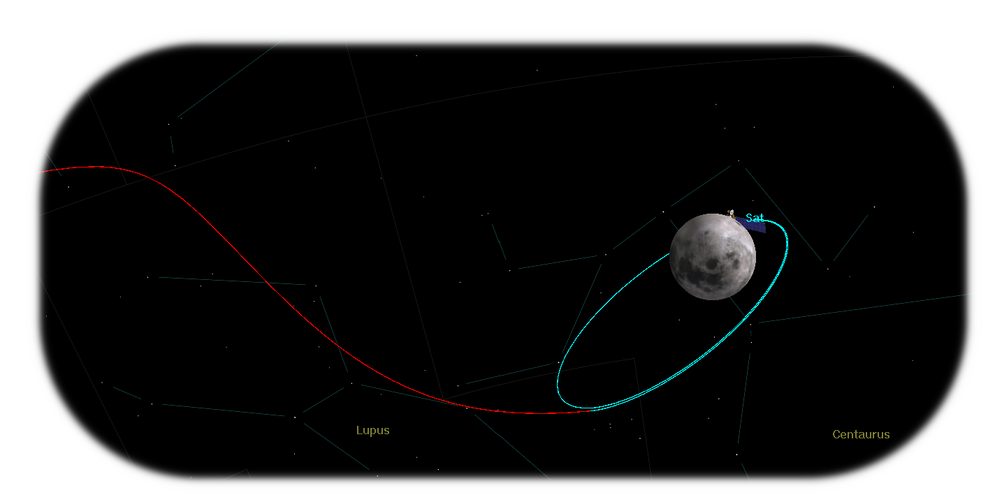
The first delta v is done to change from the trans lunar insertion orbit (TLI) to the lunar orbital insertion orbit (LOI). Using the principle of conservation of total energy, we can compute the arrival velocity at periselene as follow:
We then compute the delta v by calculating the difference between this velocity and the velocity the spacecraft should have at the desired orbit, which is obtained using the Vis-Viva equation.
- Delta-v inclination
The second delta v is used to change the inclination of the lunar orbit. The delta v is determined using the following equation:
- Delta-v deployment
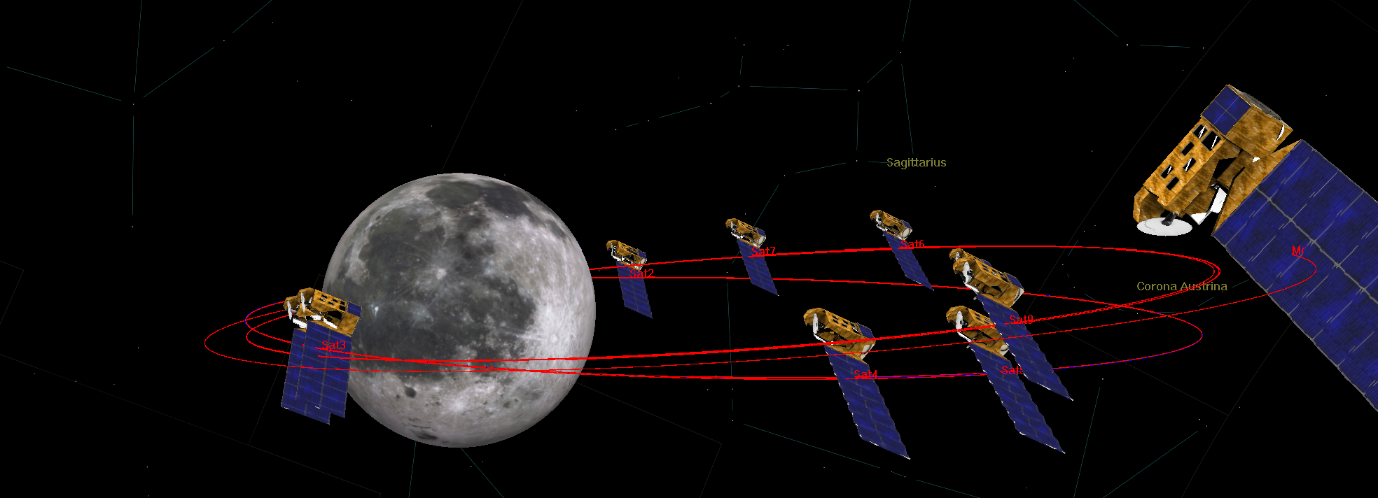
The deployment phase occurs as follows: first, the spacecraft deploys 5 satellites in the first orbit equidistantly by increasing, waiting, then decreasing its aposelene. It then performs a RAAN change (same equation as point 2.), to deploy the remaining 4 satellites in the second orbit.
The deployment strategy for the Carina mission is quite straightforward. Initially, the deployer releases the first satellites, then executes a retrograde burn at periselene to transition into a lower, catch-up orbit. This maneuver involves a retrograde delta v of 5.3 m/s, which can be calculated using the following formula.
After the burn, the deployer waits for 'N' revolutions in this orbit, which is determined by the number of satellites it needs to deploy in this particular orbit.
Coming from :
Once the waiting period is over, the deployer performs a prograde burn of the same magnitude as before, just before releasing a satellite. This process is then repeated until all the satellites are deployed.
To summarize, the deployment phase of the Carina Mission involves the following steps:
- Release satellite n°1.
- Retrograde burn, Wait for 'N' revolutions, Prograde burn.
- Release satellite n°2.
- Retrograde burn, Wait for 'N' revolutions, Prograde burn.
- Release satellite n°3.
- Retrograde burn, Wait for 'N' revolutions, Prograde burn.
- Release satellite n°4.
- Retrograde burn, Wait for 'N' revolutions, Prograde burn.
- Release satellite n°5.
- Perform a RAAN change maneuver.
- Release satellite n°6.
- Retrograde burn, Wait for 'M' revolutions, Prograde burn.
- Release satellite n°7.
- Retrograde burn, Wait for 'M' revolutions, Prograde burn.
- Release satellite n°8.
- Retrograde burn, Wait for 'M' revolutions, Prograde burn.
- Release satellite n°9.
- Delta-v end-of-life
The final delta v is used to decommission the satellite. It consists of 2 delta v raising both the periselene and aposelene by 50 km. Both are simply computed using the vis-viva equation:
- Delta-v summary
To provide a clear and concise overview of the Carina mission's deltaV requirements, we have compiled the following table:
| Mission phase | [m/s] | Description |
|---|---|---|
| LOI | 413.7 | Lunar Orbit Insertion |
| Inclination / RAAN change | 1080 | |
| Deployment | 78.1 | retrograde and prograde burns |
| EoL | 6.2 | Two prograde burns |
For those interested in the details of the deltaV calculations for the Carina mission, we have provided a [Python script]{} with all the necessary information. This script includes not only the mathematical formulas used for the calculations, but also additional information such as a precise timeline of the mission phases and maneuvers.
Eclipse duration:
Computing the duration of an eclipse during a lunar mission is a complex task due to several factors such as the altitude of the spacecraft and the eccentricity of the Moon's orbit. To account for this complexity, we have computed the eclipse duration for the worst-case scenario, where the deployer is far from the Moon and thus moving at a slower pace during the eclipse.

We can compute the eclipse duration using the following formula :
Using this formula, we have determined that the eclipse duration for our worst-case scenario is 8.2 hours and 2.6 hours of direct sunlight/communication. It is important to note that this duration may vary depending on the altitude of the spacecraft and the position of the Moon in its orbit. However, by computing the duration for the worst-case scenario, we can ensure that our lunar mission is prepared for any potential challenges that may arise.
End of life management:
In order to decommission the deployer, it has been decided to raise its aposelene and periselene by 50 km. All the other orbital parameters stay the same in order to stay at a frozen orbit. There is no defined graveyard orbit around the Moon, the most commonly used decommissioning strategy is to crash the spacecraft on the lunar surface. However, this is not a sustainable long term strategy. The spacecraft doesn’t have enough delta v to go back to Earth nor to go out of the sphere of influence of the Moon. This is why it has been decided to only raise the periselene and aposelene by 50km, as this puts the deployer in a stable orbit that does not impact any other lunar missions.
¶ Configuration
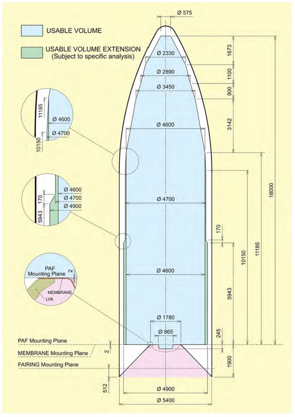
For this section, the first task was to communicate with all subsections to understand and know all hardware used and needed for the spacecraft. The second task was to identify the specific spatial requirements for each hardware and take in account the available volume in Ariane 64: 242.25 m3
It is needed to have two main configurations, one configuration during the launch when our spacecraft is attached to Ariane 64 and one when the spacecraft is deployed.
Hardware configuration:
| Hardware | Requirements |
|---|---|
| Batteries | No specific requirements but batteries will heat a lot interesting to put it near hardware that need heat |
| On board computer | Preferably located at the geometrical center |
| PCDU | No specific requirements |
| Reaction wheels | Have to be on each axes of the center of mass |
| Thrusters | Farthest possible to the center of mass to reduce the power consumption, need to cover all axis |
| Solar panels | Need a large surface 13.4 m2, need space to be oriented to face the Sun |
| Antennas | Need to be oriented to face the Earth, as isolated as possible from other components (reduce noise) |
| Tanks | Close to the rocket engine |
| Rocket engine | Close to the tanks, need to be at an extremity and cross the center of mass |
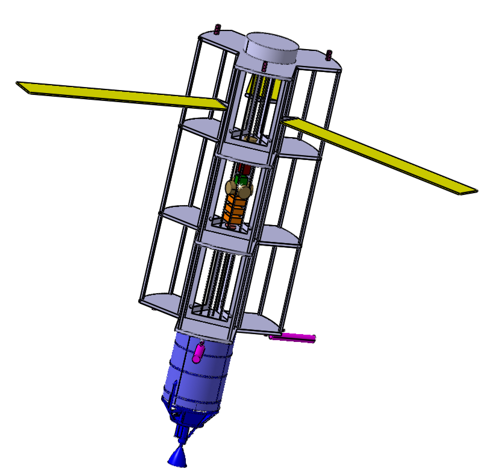

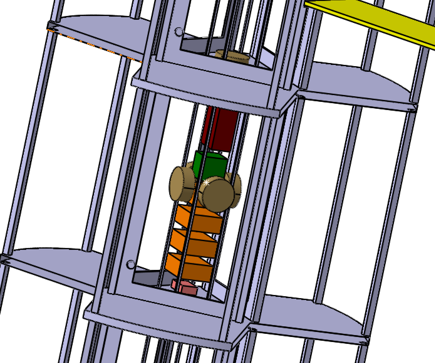

The center of mass is represented by the little white star that can be seen on the first image. The final configuration of the subsystems has been realized according to all requirements. The previous images show the chosen configuration.
Launch configuration:
As mentioned above, the volume available in Ariane 64 is limited, that's why we chose to use folding solar panels (yellow) and rotating antennas (pink).
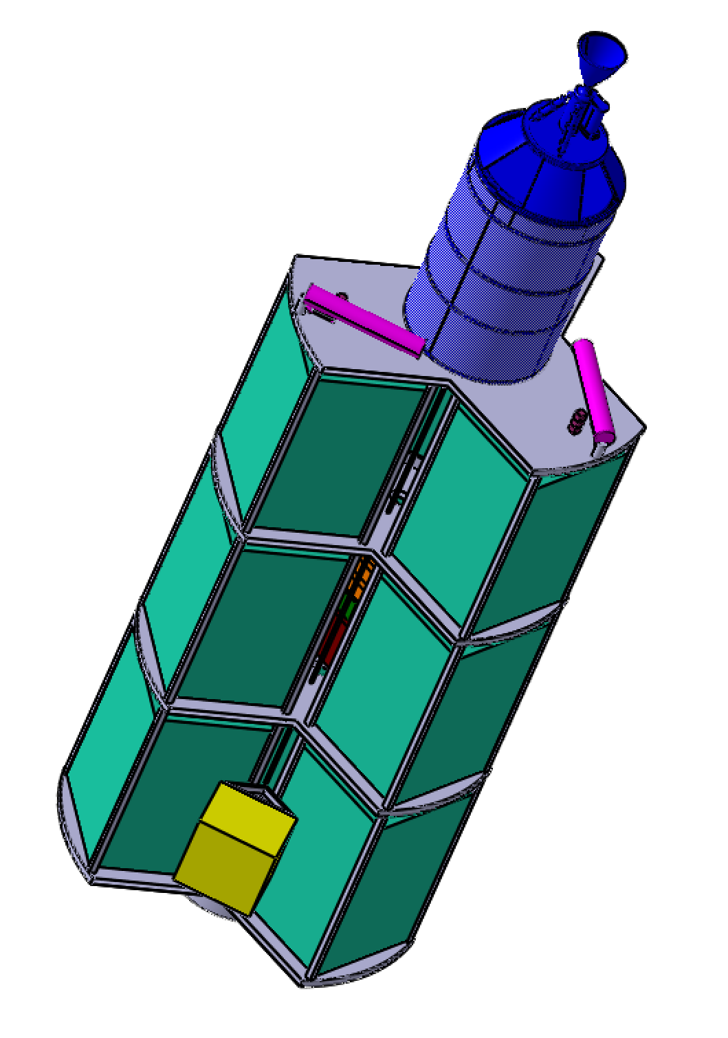
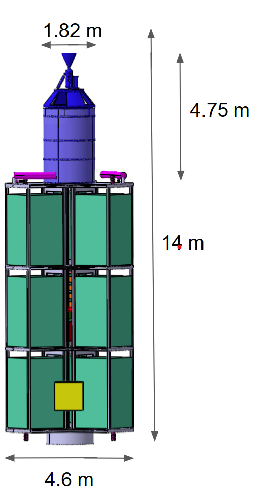
This configuration allows our spacecraft to fit in the Ariane 64 and only uses a total volume of 166 m3.
Deployed configuration:
This configuration is important because this configuration is used for all phases after the commissioning. The center of mass has to be known and carefully located to facilitate the control of the spacecraft for the AOCS subsystem and for each stage.
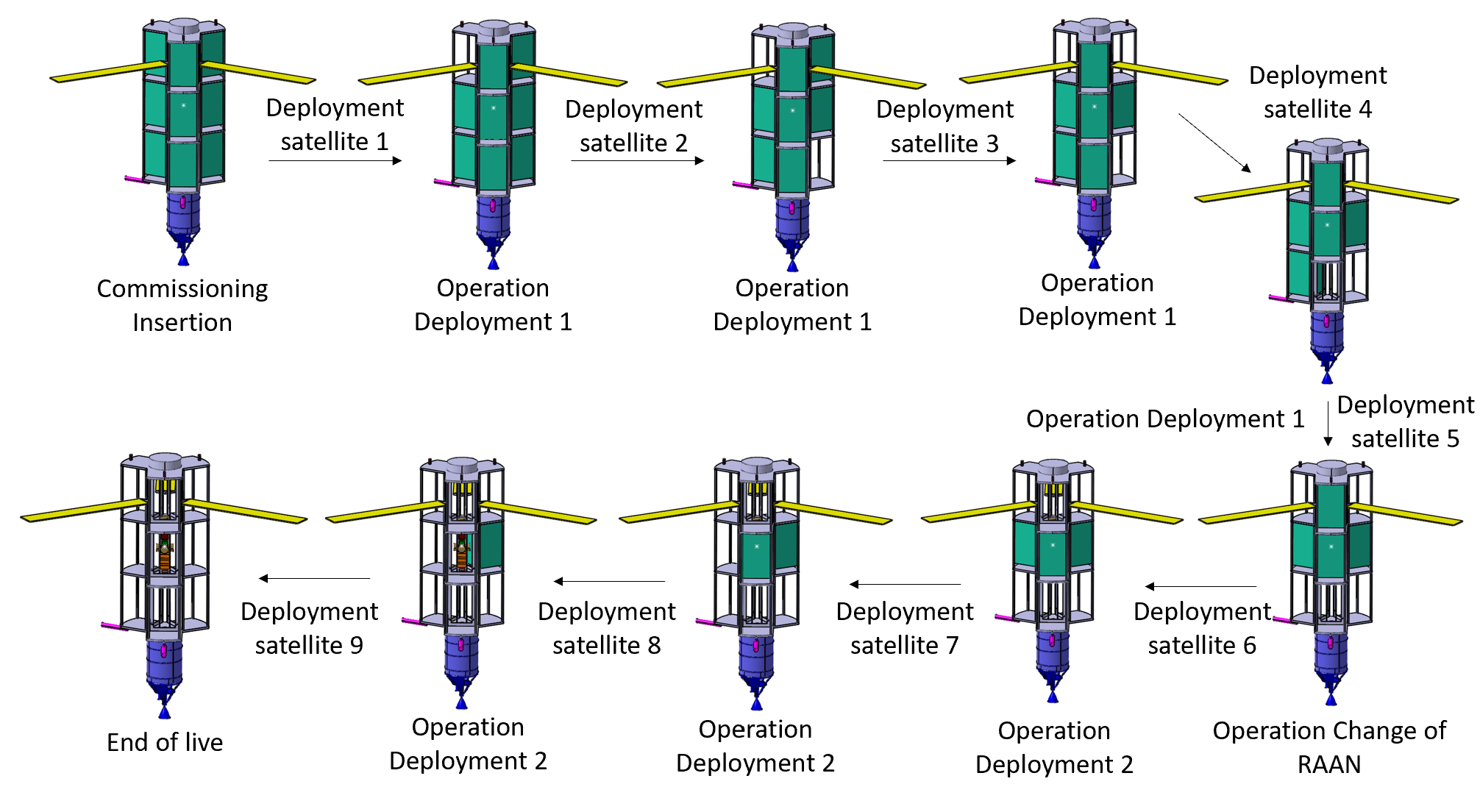
This sketch shows the different configurations during satellite deployment. During the commissioning phase, there is a transition from the launch configuration to the deployed configuration, the solar panels are deployed and the antennas rotate to face the earth. Obviously, the configuration and the center of mass will change when we deploy a new satellite. Thus, for each maneuver these changements are taken into account to control the spacecraft.
¶ Structures & Mechanisms
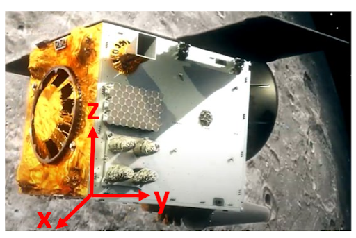
The Structure and Mechanism subsystem is responsible for designing the outer and inner structure of the spacecraft and selecting the necessary mechanisms. To begin the design process, it is crucial to consider the primary constraints. As previously mentioned in the Configuration section, one of the constraints for the structure is the limited space available inside the Ariane 64. The outer structure (without propulsion) must not exceed 11m in height and 4.6m in diameter to ensure it can fit within the launcher. Additionally, the structure must accommodate 9 pathfinder satellites, each measuring 2.5m x 1.5m x 1.5m, which can only be attached to the spacecraft's xz-plane. (Figure X). Another significant constraint that must be considered during the structure's design is the loads the spacecraft will experience during launch, which can reach up to 6g. Therefore, the structure must be highly robust and capable of carrying high loads, while still maintaining a lightweight design. The mechanisms that are included in the spacecraft are the pathfinder deployment mechanism, the solar array deployment mechanism, the solar array steering mechanism and the antenna steering mechanism.
Requirements:
- Shall define the structure depending on the configuration
- Shall estimate the loads applied depending on the configuration
- Shall design/select a separation mechanism to deploy the lunar Pathfinder satellites
- Shall design/select the Solar Array drive and deployment mechanisms
- Shall design/select the Antenna deployment mechanism
- Shall define a mass budget for the whole subsystem
Tradeoffs:
Structure
- Material choice for the loads bearing structure and subsystems accommodation (CFRP vs Alu)
- Load bearing structure’s shape and principle (Plain vs truss)
- Subsystems accommodation in accordance with Configuration (How to accommodate everyone)
- Satellite accommodation in accordance with Configuration and lunar Pathfinder’s requirements (Satellite configuration/fixation)
Mechanisms
- Pathfinder’s deployment mechanisms options
- Antenna steering mechanism options
- Solar panels steering mechanism options
- Solar panels deployment mechanism options
Justifications:
Structure
- Designing a low weight structure that is able to bear high flight loads requires the use of optimal materials. Parameters such as thermal properties shall be taken into account.
- To further improve the structure's weight and resistance, its shape is to be defined. Structures available in the industry are often plain cylinders with fixations on the side or truss assembly.
- All the subsystems have custom needs for their interfaces with the general structure. The way they are accommodated in the spacecraft depends on the structure’s type and on their design. They can be screwed on, press-fitted, clamped, etc…
- The Pathfinder satellite has a defined interface with the spacecraft. Its orientation and method of fixation directly depends on the general configuration.
Mechanisms
- The deployment of the Pathfinder satellites needs to be reliable and should not induce excessive loads on the deployer’s structure or on the Pathfinder itself.
- To ensure correct communication between the spacecraft and the command center on Earth at all times, the direction at which the antennas are pointing needs to be controlled. To reduce the constraints on the AOCS subsystem, the antennas are steered using a COTS mechanism.
- Similarly to the antenna, also the panels' orientation needs to be controlled. If the spacecraft needs to be charged, they should always point to the sun.
Results:
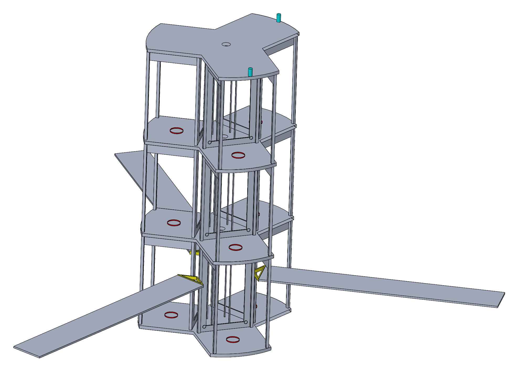
After taking into account all objectives and requirements, a first design of the possible structure was made. The following Figure X shows the structure with the different mechanisms. In red: Pathfinder deployment mechanism, in yellow: Solar array deployment and steering mechanism and in blue: Antenna steering mechanism.
Structure
The main external structure of the spacecraft consists of three identical sections, each of which accommodates three pathfinder satellites arranged in a triangular formation around the spacecraft's center. The space between the satellites is utilized to store all the electronic components. Sandwich panels, consisting of an aluminum skin on the sides of a honeycomb structure, are used to separate the three sections from each other. This material is chosen for its lightweight yet highly resistant properties. However, the minimum thickness of the sandwich panels has not been determined.
Additionally, aluminum rods are used to provide additional support to the three sections. To prevent buckling of the rods, the minimum size is calculated using Euler's buckling theorem. The critical load of Euler is determined using the following formula:
The factor 13 comes from the fact that the load is distributed over 13 rods, with each having a length of L=2.5m. By choosing aluminum 7075 the Young’s modulus is Since the cross-section of the rods is assumed to be quadratic with a hollow inside, the moment of inertia is calculated with the equation:
Where a is the outer side and b the inner side of the hollow rod.
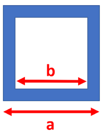
By combining the two equations, the minimum thickness can be calculated. is calculated with 6 g x mass of satellite (8500kg). Furthermore, a factor of safety (F.S) of 1.25 is included. The equation becomes:
By playing around with the value of b, a possible solution of a=8.3cm and b=8cm can be obtained, resulting in a minimum thickness of 1.5 mm. However, for the real model, a slightly larger thickness of 3mm was chosen to ensure the robustness of the rods.
Mechanisms
Pathfinder Deployment Mechanism:
To deploy a pathfinder satellite from the spacecraft, a ring separation system called SAU&RON from UARX is used (Figure X). The separation system consists of two rings that are held together by a clamping mechanism. One ring is attached to the spacecraft and the other ring to the bottom of the pathfinder satellite. When the clamping mechanism is released, the pathfinder satellite separates. The separation velocity will be about 0.2 m/s. This mechanism is light and reliable as it provides built-in redundancies.
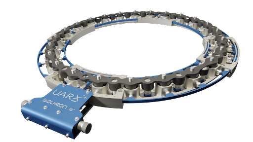
With this mechanism, the pathfinder satellite will be released upwards. To make sure that the satellite glides towards the side, away from the spacecraft, an additional custom push mechanism is needed. This push mechanism consists of a spring-loaded pin which is immediately released once the deployment mechanism is triggered.
To ensure redundancy, 4 of these pins are used to push the spacecraft. Each one is placed in a separate corner. To make sure that the pathfinder satellite does not tumble after the push, two rails are fixed to the structure of the spacecraft, where the pathfinder can slide through, in order to keep the right direction. The whole process of the deployment can be seen in the following figure:

Solar Panel Drive Mechanism:
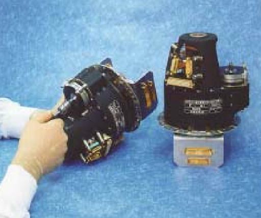
The solar panel drive mechanism positions the solar panel to face the sun for maximum energy collection and transfers the energy to the spacecraft's power system. The mechanism includes a stepper motor, a potentiometer, a slip-ring, and a reset switch. These components work together to provide precise control, feedback, and continuous energy transfer. For this mission, an off the shelf solar panel drive mechanism from ThalesAlenia was chosen. In particular, the GEO SADM Low Power, which is characterized by low weight and low power.
Solar Panel Deployment Mechanism:
The solar panels deploy thanks to a spring-loaded mechanism, integrated on the panels themselves. The panels are held closed during the first phases of the mission with a latch. Once the fairing is jettisoned and the spacecraft is on its TLI trajectory, the panels can deploy. Since the deployment mechanism can be directly bought together with the solar panels itself, no exact component has been chosen. The mass and power requirements are directly included in the budgets for the solar panels.

Antenna Steering Mechanism:
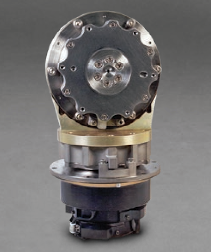
The Type 33 Biaxial Gimbal mechanism allows the deployment and the steering of the antennas. It increases the precision and reduces the constraints on the control system required to orient the antennas towards the Earth. The antennas are held against the structure during the early phases of the mission and are then steered to point towards their objective.
The table shown below, gives a summary of all the mechanical and technical details of the selected components of the structure and mechanisms:
Based on this table
| Diameter [mm] | Height [mm] | Volume [m3] | Power/unit [W] | Mass/unit [kg] | Contingencies | Mass/unit w/ cont. | # units | Total mass [kg] | Total power [W] | |
|---|---|---|---|---|---|---|---|---|---|---|
| General Structure | 4600 | 8800 | 146.247 | 0 | 447 | 0.2 | 536.40 | 1 | 536.4 | 0 |
| Deployment Mechanism | 381 | 30.80 | 0.004 | 840 | 2.30 | 0.05 | 2.42 | 18 | 43.47 | 15120 |
| Antenna Steering Mechanism | 200 | 300 | 0.009 | 500 | 3.5 | 0.05 | 3.68 | 3 | 11.025 | 1500 |
| Solar Panels Steering Mechanism | 120 | 230 | 0.003 | 10 | 4.4 | 0.05 | 4.62 | 2 | 9.24 | 20 |
| Total | 578.4 | 9080 |
¶ Propulsion
The propulsion subsystem team's role was to choose a viable option to propel the entire deployer along 4 main maneuvers: lunar orbit injection (LOI), inclination change, Pathfinders deployments and end of life. This was a complex matter given the high required for the first two maneuvers, the customer's green requirement and the total mass of the S/C. Chemical propulsion seemed like the best option but two main problems arose: the difficulty to store cryogenic propellants(boil-off) in space and the reignition of the engine. The latter was pointed out late in our study during the final presentation of the design. Some solutions that could deserve some thoughts for the next phase of this mission design are listed in the Reignition section. Given the trajectory and the mass of the S/C, it is still believed that chemical propulsion for the main maneuvers is the best choice.
Close work with the trajectory team was needed in order to optimize the along with mission time to have a good tradeoff between propellant mass and boil-off.
The starting point of the study was the analysis of the necessary to achieve our mission in an acceptable time and having short enough burn time. The needed for each type of maneuver is given in the following table.
| Maneuvers | (m/s) |
|---|---|
| LOI | 414 |
| Inclination change | 1080 |
| Satellites Deployment | 78.1 |
| End of life | 6.2 |
| TOTAL | 1578.3 |
Requirements
- Shall define the launcher, the propulsion type, the engine(s), the propellants and the tanks used.
- Shall use an european launcher.
- Shall use green propulsion. By the customer's definition, this means no hydrazine or hydrazine derivative.
- Shall maximise the lifespan of 8.5 years of the Pathfinder satellites.
- Shall perform the aforementioned within the propellant mass constraints.
Tradeoffs
- Launcher:
- Vega/C vs Ariane 62/64.
- Ariane 62 vs Ariane 64.
- Propulsion system + propellant:
- Green vs all other possibilities(Solid, electric, chemical).
- Green vs chemical.
- Chemical propellant type.
- Active cooling vs passive cooling
Justifications
¶ Launcher
The first point treated was the choice of the launcher. Two different launcher brands were possible as per the "european launcher requirement". Hence the choice was made between Ariane 6 (Ariane 62 and 64) and Vega (Vega and Vega-C). Their performances are given in the table below.
| Launcher | Orbit apogee (km) | Orbit perigee (km) | Orbit inclination | Mass (kg) | Dimensions |
|---|---|---|---|---|---|
| Ariane 62 | 400 000 | 200 | 6° | 3500 | 14xD4.6 |
| Ariane 64 | 400 000 | 230 | 7° | 8600 | 20xD4.6 |
| Vega | 1700 | 250 | 5° | 1963 | 8xD3 |
| Vega C | 700 | 700 | - | 2200 | 9xD3 |
To make the selection, the cost minimisation wanted by the customer was preponderant. As such, the number of launches needed to be minimised and the number of satellites sent per launch had to be maximised. Moreover, to have an acceptable GPS/Navigation coverage, at least 3 satellites on 2 different stable Moon orbits are necessary. With 6 Pathfinders of 330 kg each, the payload was fixed. From these mass statements only, the Vega launchers were dismissed.
To make the tradeoff between the 2 Ariane launchers, a first rough computation was performed assuming a payload of 6 Pathfinders and using the maximal mass the two different launchers could put in a Trans-lunar injection(TLI) trajectory. Assuming a common around , the available dry mass for each launcher version given the above and the maximal performances of the launchers was computed using the rocket equation:
This gave the team a first approximation of a dry mass and the optimisation/design path to choose. The result of this study is shown below.
| [m/s] | (A-62)[kg] | (A-64) [kg] |
|---|---|---|
| 414.0 | 397.7 | 977.3 |
| 1080.0 | 837.6 | 2058 |
| 78.1 | 51.0 | 125.2 |
| 6.2 | 4.00 | 9.82 |
| Total propellant | 1290.2 | 3170.3 |
| Dry mass usable | 230 | 5330 |
From this table, the mass that can be used by the different subsystems of the deployer S/C is 230 kg with Ariane 62 and 5330 kg with Ariane 64. As a consequence, A-62 would require two launches of 3 satellites whereas A-64 would require one single launch with 6 satellites. Given the ~10'000 $/kg cost for Ariane 6 launches, a single launch is better for the customer.
After a first iteration of the full design of the S/C, the decision was taken to send 9 Pathfinders with a single launch. This precipitated the decision to use A-64.
¶ Propulsion type + propellant
The launcher provides the TLI. The remaining maneuvers are LOI, inclination change, satellite deployments and EoL. The first two maneuvers require a high and as such ask for a high thrust or a high specific impulse and/or the best of both. The mass constraints required an effective system too.
Apart from the green requirement, the other points of decision were the complexity of the system and its reliability.
¶ First selection
Some propulsion systems could be discarded without having to do a proper tradeoff. Indeed, given that the LOI and inclination changes are highly demanding in acceleration, one idea was to use a kickoff solid propellant stage. However, given the mass of the S/C at the moment of maneuver, the biggest kick stage available on the market (Star 48 by Thiokol) lacked 30% of potential. Its mass with respect to its performance wasn't good enough too with a low specific impulse. All hydrazine-derived engines were discarded by principle.
The remaining propulsion types required some proper tradeoff: chemical, electric and green. Below are some pictures of some of the pretenders engines.
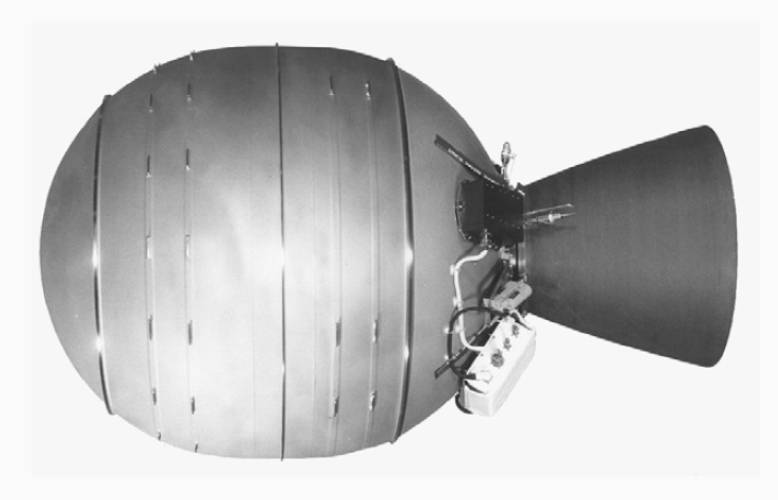
Thiokol Star 48

Aerojet Rocketdyne GR-22(right): ISP: 255 s, Thrust: 22N, Mass: 1.1 kg
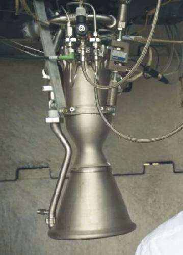
Rutherford engine: ISP: 343 s, Thrust: 26kN, Mass: 35 kg.

Bradford HPGP 200: ISP: 234 s, Thrust: 200N, Mass: 6 kg
¶ Criteria
This section describes the criteria used for the tradeoff using ESA's calculation sheet. The following weight order was used:
Availability = Thrust = Complexity = = Risk > Mass = Stockability.
The range for each criteria goes from 1 to 5. 5 meaning that it is a good choice with respect to the criteria and 1 a bad choice.
Availability: Is the engine available ? Is it flight-proven ? What's its TRL ?
Thrust: Is the engine's thrust enough to do the mission in a reasonable amount of time given the Pathfinder's lifespan ?
Complexity: How complex is it to integrate this system in the S/C with respect to the mass budget and the interconnectivity with the other subsystems ?
: What's the engine's specific impulse ? So its efficiency.
Risk: What are the intrinsic risks of using such an engine ? It's reliability and also the extrinsic risks: if there is a problem, how does it impact the other subsystems and the success of the mission ?
Mass: Does the engine fit within the mass budget ?
Stockability: Is the propellant easily stockable ? Given that the biggest maneuvers are at the beginning, the evaporation is a medium-sized problem.
¶ Tradeoff
The tradeoff table is shown below. A radar plot is shown right after.
| Rutherford - naked | Bradford HPGP | GR-22 | Rutherford + active cooling | Other chemical | Electric propulsion | |
|---|---|---|---|---|---|---|
| Availability (TRL) | 5 | 2 | 4 | 3 | 5 | 5 |
| Thrust | 5 | 4 | 1 | 5 | 5 | 1 |
| Complexity | 3 | 3 | 3 | 4 | 3 | 3 |
| I_ | 3 | 4 | 4 | 2 | 4 | 5 |
| Risk | 4 | 4 | 3 | 3 | 3 | 5 |
| Mass | 4 | 3 | 3 | 3 | 1 | 5 |
| Stockability | 2 | 5 | 5 | 5 | 1 | 5 |
| Total score | 3.95 | 3.43 | 3.05 | 3.43 | 3.86 | 3.86 |
| Ranking | 1 | 4 | 6 | 4 | 2 | 2 |
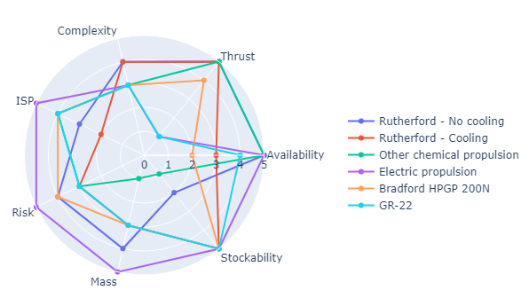
Justifying each criteria exhaustively here would be too long. Here are however some of the main arguments for the ranking:
Rutherford - naked: Readily available. TRL 9. Flight-proven. High-thrust: 26 kN. Complexity: requires batteries, needs at least one reignition(this problem was answered only at the end of the study). High-enough specific impulse because it uses cryogenic LOX. Mass: only 35kg. Bad stockability of LOX in space(see boil-off related section).
Bradford HPGP: Low TRL: 5. Medium thrust: 200N per engine. Would require a cluster so adds complexity and mass. Purely green so good stockability, good risk.
GR-22: Available but not strong heritage. TRL 8+/9. Thrust way too low: 22N so requires a cluster. This adds complexity and mass. Purely green too.
Rutherford + active cooling: Same as naked Rutherford but active cooling is in its early stages. Adds mass and complexity and risk but very good stockability.
Other chemical: Same as Rutherford except that it is way heavier(+150/200 kg). Better specific impulse usually because uses LH2/LOX or CH4/LOX but worse stockability as both fuel and oxidizers are cryogenic.
Electric propulsion: Excellent everywhere but thrust. Given the masses engaged and the timeline, it is rather difficult to accustom it to the mission. It would take years to do the computed. Needs high power output.
¶ Propellant type and motor choice
Given the precedent table, the Rutherford engine in its vacuum configuration was chosen. The Rutherford engine has good specifications but it uses LOX, a cryogenic material, that poses other problems such as boil-off.
Indeed, LOX has the tendency to evaporate and this is one of the main reasons why it isn't used (and other cryogenic elements) on long-run space missions. This engine also uses electrical turbopumps. This has the advantage of removing the need for pressurisation but it requires powerful and heavy dedicated batteries which increases the mass budget although the engine is light and limits the burn duration. Another problem that was identified only too late in the design was that the Rutherford engine cannot be reignited in its original vacuum configuration. The following sections describe these two problems. The first one is provided with a solution that was included in the final mission design. The second problem wasn't tackled thoroughly and is left to the next design phase. Only lines of thought are given.
¶ Boil-off
Using cryogenic propellant, although very efficient, has its drawbacks. Indeed, it is difficult to stock since it evaporates. This is called the boil-off. As LOX has a boiling temperature of 90.8K at 1 atm, it evaporates in the tanks, even with state-of-art passive insulation, at a rate too high to consider using it for a mission longer than a couple of weeks. This results in the too high pressurisation of the tanks which have to be vented periodically. To mitigate the LOX boil-off in the tanks, two types of techniques can be used:
- Active cooling systems such as cryocoolers
- Passive cooling such as multi-layer insulation (MLI).
Active cooling is very new and isn't flight-proven. Studies are being made but its TRL is still in the 5-6 range depending on the systems. Moreover, it adds mass and complexity. A tradeoff was made between simply adding more propellant with MLI to compensate for the loss over the duration of the mission and using an active cooling system(See the table above). It was also asked by the trajectory team if a faster timeline between deployments was possible. This was done and the mission timeline was reduced by ~20%. Below are the computations performed to estimate the propellant lost each day and between each maneuver and how to account for it.
The boil-off rate in percentage of the volume of propellant lost per day is given by the following formula:
where is the heat-flux received by the tank, is the volume of the tank, is the density of LOX and is the vaporisation enthalpy of LOX at 1 atm. To compute the heat flux on the tanks, it was assumed that they were spherical and made of T87-2219, mm thick aluminum($\kappa_{alu} = 121[W/mK] $) covered with of aluminized polyester film with a thermal conductivity of . The heat-flux, assuming the layers of MLI and aluminum to be in series, is given by:
where $\Delta T $ is the temperature difference between the interior of the tank and the exterior. The interior is assumed to be at 1 atm with a temperature of 90.8K, the boiling point of LOX. The resulting plot is shown below:
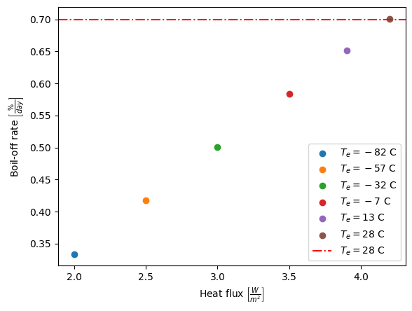
MBoil-off rate as a function of Heat flux Q for different temperature regimes. Worst-case scenario as given by thermal specialist is 28°C.
For the worst case scenario of 28°C given by the thermal team, the boil-off rate is 0.7%. The value found in the literature is between 0.5-1%. It was therefore decided to go with 1.05% since this calculation relied on a lot of approximations. Had we found a higher value than the literature, the latter would have been used.
The effect of boil-off can be seen in the following plot showing the mass of propellant left as a function of the timeline of the mission.
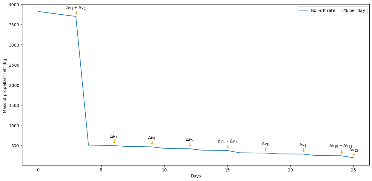
Mass decrease along time due to boil off and maneuvers
¶ Reignition
The Rutherford engine is not reignitable. The few options available for a green and powerful engine made the subsystem team neglect this important aspect up until the end of the study. Without changing completely the timeline, here are some lines of thought on possibilities to tackle this problem:
- Usage of Ullage motors. Propellant have the bad habit of sloshing around in the tanks in vacuum which causes them to get away from the point of suction of the engine. One way to avoid that is to use small rocket engines to cancel the zero-G environment and force the propellant into the engine.
- Since the biggest maneuvers are the two first ones. It would be a good idea to investigate the use of small solid propellant motors for the satellites deployments and the S/C end-of-life. This would also avoid the attitude maneuvers necessary to point the engine in the right direction for each of the deployments. The solid rocket boosters could be placed adequately by knowing in advance the direction of thrust necessary for each deployment maneuver. This solution would mean that the Rutherford engine would need to be reignitable only once which is easier to do than nine times.
- The usage of the RCS, if powerful enough, can be done as Ullage motors too.
¶ Tanks
The tanks are spherical for the LOX and cylindrical for the RP-1. This is to reduce the heat received by the LOX tank as the spherical geometry is the most optimised and has the best surface to volume ratio. This reduces boil-off compared to other geometries. The shape of the RP1 tank was studied too. To save mass it could have been a spherical shape, however as the RP1 tank has twice less volume it would have needed a heavier interface between the two tanks. Hence a cylindrical tank with the same shape was chosen. By doing so the length of the spacecraft is lowered and its rigidity increased. Below are shown previews of the tanks.
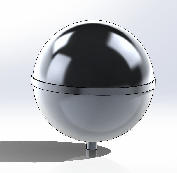
Spherical LOX tank in aluminum
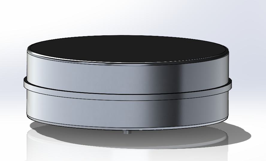
Cylindric RP-1 tank in aluminum
The LOX tank is placed above the RP-1 one to avoid the heat exhaust from the engine mostly. This is a configuration seen in a majority of spacecraft.
The thickness chosen for the tanks is in the range of the average thicknesses found in the literature. Idem for the insulation layers. The material used, T87-2219 aluminum alloy, is the most common one used for such propellant tanks too.
There was however some hesitation between an aluminum alloy and titanium given the pressure that would have occurred in the LOX tanks. However the greater price of the titanium didn't balance its higher resistance in this application as the pressure in the tanks would have been quite low ( bars). On the following table, a comparison between both metals is shown.
| Material | Density | Price | Hardness |
|---|---|---|---|
| Aluminum | 0.60 CHF/kg | 15 HB | |
| Titanium | 4.60 CHF/kg | 70 HB |
In space insulations are composed by multiple layers of reflective films to reflect radiations. In the following table are several materials used in comparative studies by NASA.
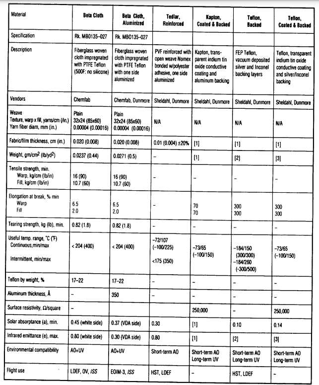
Insulation materials comparison
For this study, a MLI insulation type with aluminized polyester film was chosen. It has a total thickness of 0.5cm for 40 layers and a conductivity of .
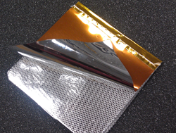
MLI aluminized beta cloth
Results:
¶ Launcher
Choice: Ariane 6 in its A-64 configuration is chosen to carry the 9 Pathfinders up to TLI in a single launch.
¶ Propulsion system + propellant type
Choice: The Rutherford engine in its vacuum configuration was chosen thanks to its low mass, high specific impulse and thrust. A maximal thrust time of 4min48s was computed for the second burn which suits the needs of the trajectory team. The propellants used are RP-1 and LOX. The masses computed assumed a typical 2.67:1 oxydant:fuel ratio. The total masses of fuel/oxidizer are 977kg and 2610kg. The propellant mass without boil-off would have been 3153kg. Here it is 3587kg.
The characteristics of the engine are shown below:
| Motor | Rutherford |
|---|---|
| Mass (kg) | 35 |
| Thrust (kN) | 26 |
| ISP (s) | 343 |
| Propellants | RP1/Lox |
| Diameter (cm) | 35 |
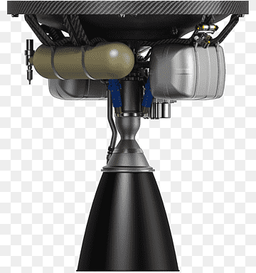 Rutherford engine: ISP: 343 s, Thrust: 26kN, Mass: 35 kg
¶ Tanks
Choice:
- A spherical tank of radius 0.81m, 4.8mm thick of aluminum alloy T87-2219, volume $2.13m^3 $ and a total mass of 107.48kg with 40 layers of aluminized polyester film was chosen.
- A cylindrical tank of radius 0.81m, height 0.58m, 4.3mm thick of the same alloy, volume $1.12m^3 $ and a total mass of 81.71kg with 40 layers of the same insulator was chosen.
To keep a reasonable complexity it was chosen to only use passive cooling in the oxygen tank (i.e insulation and venting). Venting will be stopped before maneuvers to pressurise the LOX tank more than the pressurisation of the turbo pumps.
The final dry mass of the propulsion subsystem is 306.85kg with an accounted 25kg for valves, tubing etc... This total mass doesn't count the additional mass Ullage motors or mini-rocket boosters would add and that are most likely to be needed to reignite the engine. This is left for the next more detailed phase of the study.
¶ Margin philosophy
Dry mass of the system
A margin of 5% was applied.
Boil-off rate
A margin of 5% was applied on the literature value and 30% on the computed value.
Propellant mass
A margin of 5% was applied on the total propellant mass with boil-off.
Tanks
A margin of 5% was applied on the volume of the tanks.
References:
- Alu: https://asm.matweb.com/search/SpecificMaterial.asp?bassnum=MA2219T87
- MLI:
- https://iopscience.iop.org/article/10.1088/1757-899X/396/1/012061/pdf#:~:text=The effective thermal conductivity of,conduction modes of heat transfer
- https://www.dunmore.com/products/aluminized-polyester-film.html - Boil-off: https://www.mdpi.com/2077-1312/9/1/36
¶ AOCS
Requirements:
- The S/C shall align its x-axis to NADIR with a pointing accuracy less than 2.2°.
- The S/C shall align its y-axis to the sun with a pointing accuracy less than 10°.
- The S/C shall be stabilized around its roll axis.
- The AOCS subsystem shall have a mass less than 220kg.
- The AOCS subsystem shall use less than 1kW of power.
- The AOCS shall operate at least 15 slew manoeuvres (a slew manoeuvre is defined as a 180° S/C attitude change).
- The AOCS subsystem shall perform each slew manoeuvres in less than 10 minutes.
Tradeoffs:
AOCS actuator configuration (momentum wheel vs reaction wheel vs thrusters vs magnetic torquer):
- Versus weight
- Versus manoeuvre slew time (time to make a 180° S/C rotation)
- Versus life-time
AOCS sensor configuration:
- Versus weight
- Versus price
Redundancy:
- Versus weight
- Versus peak power
- Versus price
Justifications and results:
¶ AOCS actuator configuration
The selection of the AOCS actuators depend on the mission requirements and was optimized with respect to the system weight, the manoeuvre slew time and the operational life-time of the system.
For this purpose, the mission trajectory can be subdivided in two phases. The first one occurs after separation with the A64 launch vehicle and lasts until the lunar orbit insertion. The second one is an orbital trajectory around the Moon and lasts for the deployment of the Pathfinder satellites. Since the CDHS antennas are aligned with the S/C largest axis of inertia, the torques created by the earth’s gravity during the first phase will assist the S/C into orienting its antennas towards the earth. In other words, only the second phase of the mission trajectory was analyzed to size the AOCS actuators.
¶ Orbit maintenance
In lunar orbit, the S/C trajectory is mainly influenced by the solar pressure torque and the gravity torque. The drag forces are neglected because the atmosphere around the Moon and at the S/C altitude is extremely thin and there is no magnetic field, thus no magnetic torque, around the Moon.
The solar pressure is due to the flow of photons from the sun to the eccentric surfaces on the S/C. To simplify the computation of the resulting torque, only the largest moment arm and largest exposed surface are considered. In the case of our S/C, the moment arm is 0.6m and the exposed surface is 6.12m^2.
The gravity gradient is due to the fact that the Moon is not spheric. Because it is rotating, the mass density is larger around the equator than around the poles, meaning that the gravitational force is larger when the S/C flies over the Moon’s equator. This change in force along a trajectory induces a torque to the S/C that must be accounted for in the AOCS subsystem.
The following figure depicts the evolution of the torque affecting the S/C due to the Moon’s gravity gradient and the solar radiation pressure.
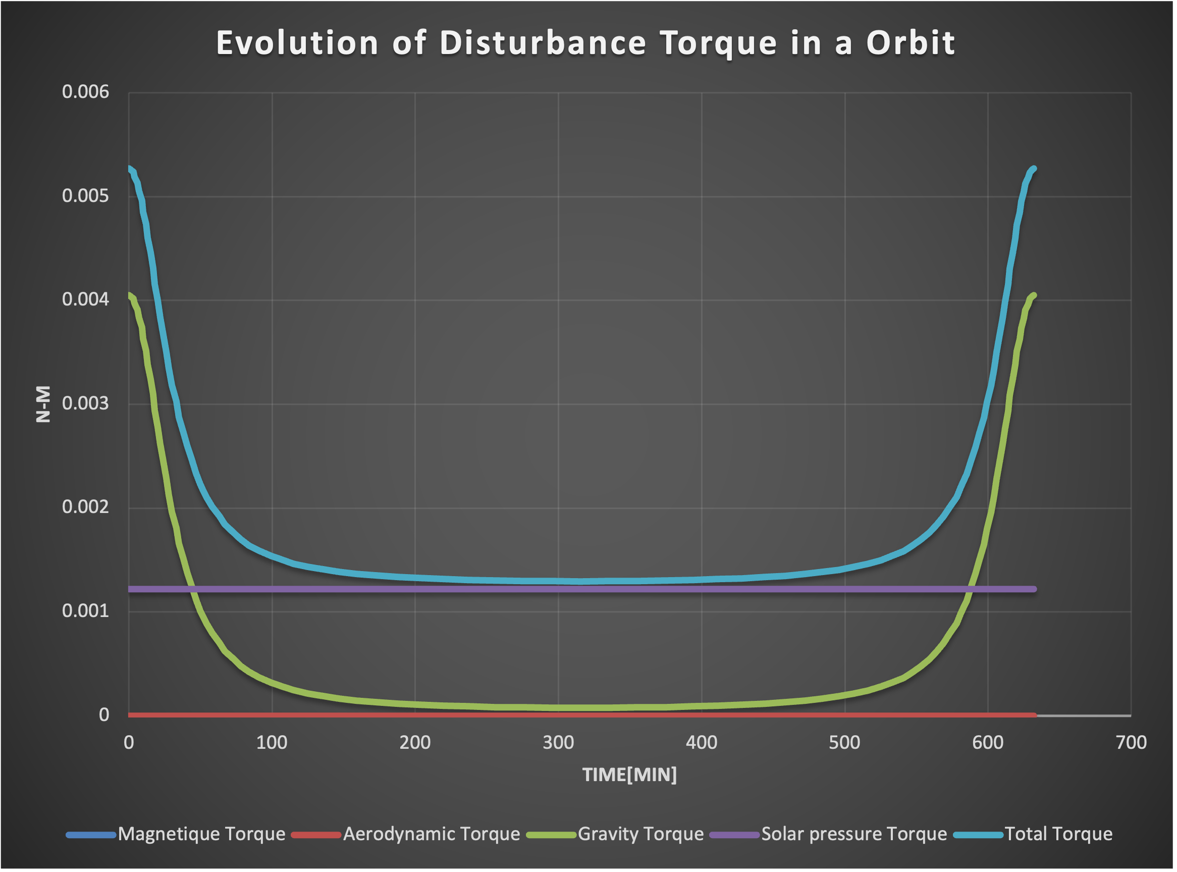
Evolution of disturbance torque in an orbit
The peak torque that the orbit disturbances apply to the S/C are 5.3mNm and the accumulated angular momentum during one orbit is 3.3Nms (the integrated torque). For the whole mission, which consists of 48.5 orbits, the total angular momentum is 160Nms.
¶ Slew manoeuvres
In order to fulfill the mission requirements, the S/C will have to perform retrograde and posigrade burns thanks to the propulsion subsystem. The AOCS has to account for the orientation of the S/C to the right attitude before propulsion can ignite their engine.
A so-called slew manoeuvre can be defined as an attitude change that will rotate the S/C by 180°. This is considered as being the worst-case attitude change the S/C will have to perform between the Pathfinder deployments. The associated slew time is the duration during which the AOCS will perform a 180° rotation.
¶ System sizing
To sum up, the AOCS has two functions:
Maintain a given orbit and account for the gravity gradient and solar radiation pressure
Steer the S/C to allow orbital manoeuvres.
The main design driving factor for the maintenance of the orbit is the instantaneous torque and the accumulated angular momentum.
The driving factor for the S/C steering is the slew time and the accumulated angular momentum.
Since this mission requires at least 14 slew manoeuvres, it was decided not to use any momentum wheel, which would have stabilized the S/C trajectory, at the cost of requiring a higher torque for steering the S/C. Additionally, using momentum wheels would have increased the mass and cost of the subsystem.
However, reaction wheels are used to perform slew manoeuvres since they provide a high torque that can steer the S/C in a relatively short time. For this purpose a HR16-100 reaction wheel from Honeywell has been selected.

Selected reaction wheel (HR16-100)
| Parameter | Value | Unit |
|---|---|---|
| Momentum | 100 | Nms |
| Torque | 0.4 | Nm |
| Interface | Analog/Digital | - |
| Steady power | 22 | W |
| Mass | 12 | kg |
| Operational temperature range | -30 to 70 | °C |
For maximum efficiency, three of these reaction wheels must be placed in the center of inertia of the S/C, perpendicular to one another. Such a triad would allow the control fully the attitude of the S/C. The total torque that such a triad would achieve is . This torque is much larger than the torque experienced by the S/C because of the gravity gradient and the solar pressure. As far as the instantaneous torque is concerned, this reaction wheel can be used for orbit maintenance.
Now, the angular momentum capacity must be larger than the mission’s accumulated angular momentum (160Nms), plus the angular momentum required for a slew manoeuvre.
If the S/C is subject to torques along a single axis, only one reaction wheel will store this angular momentum. It is clear that the reaction wheels are not sufficient to maintain the S/C orbit during the whole mission. Indeed, the reaction wheels must be desaturated by another actuator.
For this, additional low-thrust warm-gas thrusters are used. The Starling-1U thruster from Dstar was selected. To compensate for each rotation axis and each direction, it is necessary to have 6 thrusters to fully control the angular momentum of the S/C.
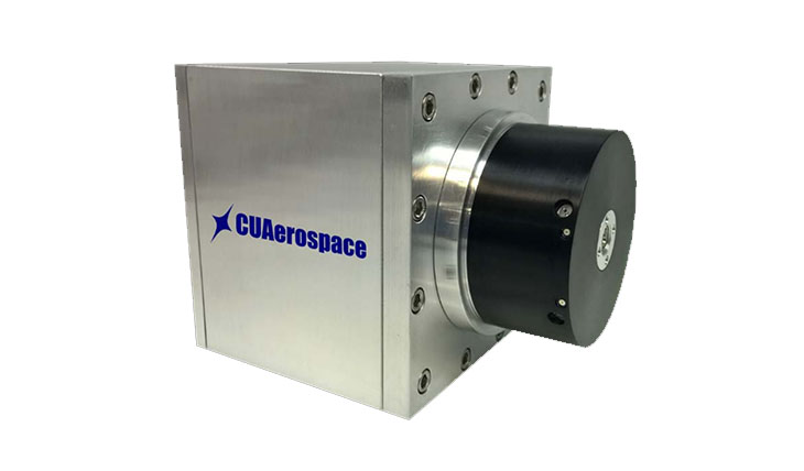
Selected hot-gas thruster (Starling-1U)
| Parameter | Value | Unit |
|---|---|---|
| Total impulse | 180 | Ns |
| ISP | 140 | s |
| Idle power | 10 | W |
| Pre-heat power (10 min) | 22 | W |
| Active power | 3 | W |
| Mass | 1.5 | kg |
¶ AOCS sensor configuration
Recalling the pointing requirements for the S/C:
- The S/C shall align its x-axis to nadir with a pointing accuracy less than 2.2°.
- The S/C shall align its y-axis to the sun with a pointing accuracy less than 10°.
The dynamics of the S/C are estimated thanks to a gyroscope, so that the S/C attitude can be correctly set before performing a main propulsive manoeuvre. The selected gyroscope is a Cirus-Ex from L3Harris, because of its very high accuracy and embedded redundancy.
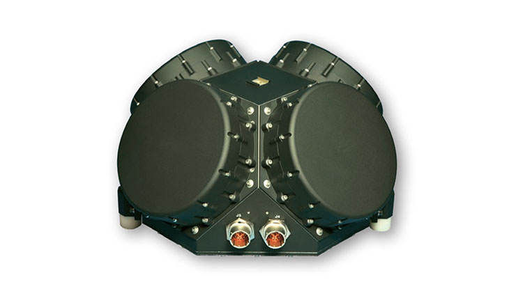
4-ways redundant gyroscope
| Parameter | Value | Unit |
|---|---|---|
| Bias stability | 0.0003 | °/hr |
| Angle random walk | 0.000019 | °/\sqrt |
| Angle white noise | 0.0000025 | arcsec/\sqrt |
| Power | 40 | W |
| Mass | 16.8 | kg |
| Operational temperature range | -23 to 41 | °C |
The accumulated bias of the gyroscope must nonetheless be accounted for. It is thus necessary to have sensors that can estimate the pointing error. A PID or similar control methods can then be used to minimize this error by controlling the actuators in closed-loop. Since the design of this control system requires accurate models of the sensors and actuators, it was decided to neglect this aspect of the subsystem in the context of this CDF study.
To lock to the earth and to the sun, at least a sun sensor and an earth sensor that fulfill the requirements must be used. The selected sun sensor is a Bison64 from Lens R&D with an accuracy of 0.5° at 3σ. The selected earth sensor is a MiDES-G from Servo with an accuracy of 0.025° at 3σ. The mass, price and power of these devices are negligible with respect to the other components of the system.
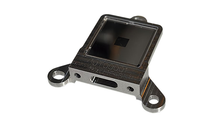
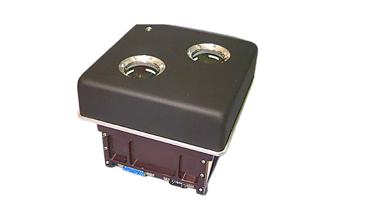
Sun sensor (left) and earth sensor (right)
It was decided to avoid using a star-tracker, since it is expensive and there are no pointing requirements when the sun and the earth are out of line-of-sight.
¶ Redundancy
The redundancy of the AOCS subsystem is enforced by design, by using multiple sensors and actuators that allow one or more failures. The decision on how many failures the AOCS subsystem should mitigate was driven by the mass and price budgets.
The final AOCS subsystem configuration is depicted in the table below:
| Part | Instances | Embedded redundancy |
|---|---|---|
| Gyroscope | 1x | 4-ways |
| Sun sensor | 4x | 1-way |
| Earth sensor | 4x | 1-way |
| Reaction wheel triad | 2x | 1-way |
| Thruster triad pair | 3x | 1-way |
In all cases, a final 4-ways redundancy was implemented for the attitude sensing, whereas a 2-way redundancy was implemented for the actuators. Nevertheless, due to the geometry of the S/C, it was necessary to implement a 3-way redundancy for the thrusters triad pairs.
¶ CDHS
This section described the design choice of the Command and Data Handling Subsystem (CDHS) including the Telecommunication parts which are responsible for the transmission, reception, and processing of data, as well as the control of the deployer spacecraft operations.
Requirements:
- The deployer shall provide telemetry to Earth ground stations, allowing to assess its state and status of the mission during each phase.
- Each function of the deployer shall be commandable from an Earth ground stations during each powered phase of the mission. It includes Propulsion and ADCS functions.
- The handling system must be designed to ensure that the spacecraft can be safely operated and maneuvered as needed.
- CDHS components shall be designed to withstand all environmental conditions encountered during all the mission phases, for example when crossing the van-Allen belt.
- The Telecommunication subsystems shall ensure electromagnetic compatibility with the Lunar Pathfinder satellites, the on-board electronic components and the ground stations network.
- Good to have: The deployer should be able to send a reliable confirmation of the Lunar Pathfinder satellites deployments, for example a picture or short video.
Tradeoffs:
The design of a CDHS (Command and Data Handling System) including the Telecommunication subsystem for a spacecraft that is intended to deploy Lunar Pathfinder satellites around the Moon involves various trade-offs. Here are some of the main trade-offs encountered during the design process:
-
Power consumption vs. computing capability/data rate: The CDHS and Telecommunication subsystems need to have sufficient computing capability and data rate to perform all necessary functions, but the more capability and rate, the more power consumption, memory and system complexity.
-
Radiation tolerance/reliability vs. cost: The deployer crossing the van-Allen belt, radiation-tolerant components ensure better reliability, but they are more expensive and heavier.
-
Redundancy/reliability vs. weight: Redundancy is essential to ensure the reliability of the system, but it adds weight and power consumption for example when duplicating the components.
-
Compatibility/standardization vs. flexibility: Compatibility with other subsystems and ground-based systems is necessary, but standardization/regulation may limit flexibility for example when choosing the modulation/communication protocol to gain range.
-
Antenna size vs. range: Larger antennas provide better range due to their larger directivity but add more weight to the spacecraft.
-
Frequency band vs. data rate/antenna size: Higher frequency bands offer higher data rates (bandwidth) but results in shorter ranges and thus require larger antennas.
Overall, the design of these subsystems requires balancing these trade-offs to optimize the system's performance, reliability, power, cost, weight, compatibility, while meeting mission requirements.
Justifications:
Regarding the requirements presented above, a Telecommunication and Command and Data Handling subsystem is necessary to safely conduct the mission, i.e. deployment of the Lunar Pathfinders satellites.
A telecommunication subsystem is then required to check the nominal operation of the deployer and its subsystems as well as to check the health of each payload satellite before releasing it.
It should also be able to receive commands from the Earth in case of encountered issues.
Thus, a data budget needs to be firstly estimated.
Note that as the Lunar Pathfinder are from a private company, data rate are roughly estimated and need to be better estimated with the customer in the next mission design phase.
Otherwise, the deployer housekeeping and Attitude data from all subsystems are considered as well as some possibilities of image/video transmission.
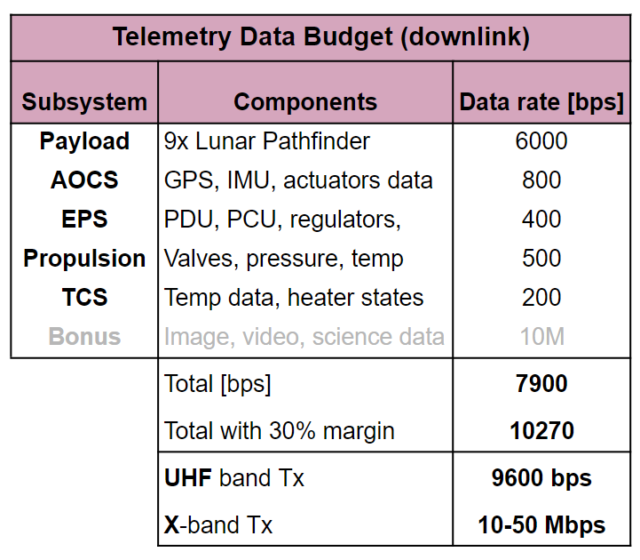
Data Budget
Results:
Here comes the big trade-off of telecommunication system: speed vs power consumption vs range.
The goal is to optimize the speed for the given range while minimizing the power consumption.
Therefore, in order to have a reliable system, i.e. a large link budget margin, at the cost of low speed, a low frequency system is often highly recommended.
It is actually really suitable for low data rate downlink telemetry or for uplink telecommand.
The drawback would be the size and mass of the antennas considering the wavelength, but looking at the deployer size, it is not a problem.
In addition, given the small additional cost, mass, and power required to integrate a high-throughput X-band telecommunications system, this system would provide significant benefits and enhance the overall mission. It could allow the transmission of high-quality images or even live video streams, and would facilitate the potential expansion of the mission for science payloads, such as university projects.
For the On-Board Computer (OBC), it was chosen to go with a classical state-of-the-art computer as nothing special is required for this mission as usual spacecraft operations.
Also to support the European and Swiss market, the selected OBC is from Beyond Gravity which proposed the Next Generation On-Board Computer (OBC NG) that is fully redundant and designed for space use. The OBC NG is based on the radiation hardened CREOLE ASIC and includes a fault tolerant SPARC® V8 processor, communication functions, reconfiguration function, and mass memory controller. It is low in mass, volume, and power consumption, and is qualified for space environment. The OBC NG has been successfully used in various LEO, MEO, GEO, and interplanetary spacecraft for decades. It also offers multiple options and interfaces, and has a processing memory of 512 MiB with EDAC and file/data storage of 2 x 374 Gbit with EDAC.
It is also very modular to facilitate future adaptations.
Furthermore, as the main risk assessment for the CDHS is to encounter communication loss or hardware failure, a good mitigation is to duplicate all the components to ensure high reliability.
Therefore, as shown on the diagram below, the X-band and UHF modules are duplicated, as well as their respective antennas.
The on-board computer is by design fully redundant as it is composed of stacked layers which can each of them be a replication or a different redundant computer depending on the cost the customer wants to invest to achieve a certain reliability level.
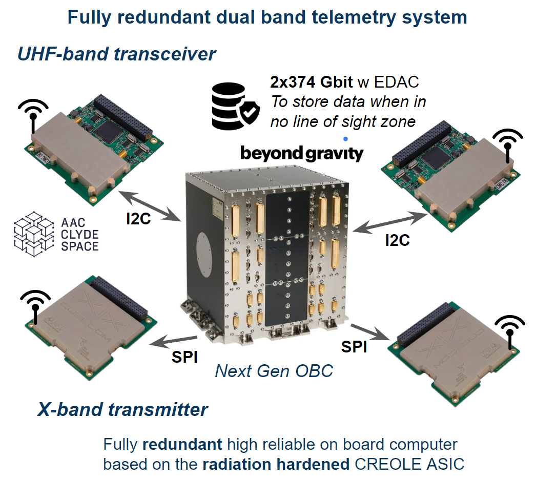
CDHS Harware diagram
¶ Antenna design
Regarding the mission, the communication to the Earth needs to operate from when the deployer is released from Ariane 64. This means that to minimize power consumption, the optimal way is to have directional antennas.
Considering the distance between the Moon and Earth, this beamwidth could even go to 2-5°.
However, as is it too small and would require a very precise and accurate pointing mechanism, it reduces the transmission reliability.
Patch antenna are good but struggles to achieve high gains.
For the first iteration, the choice to be made is more between parabolic and helical antennas.
It was decided to go for the helical antenna because it is lighter and achieves more easily circular polarization which in our case is beneficial, as for the receiver, in the worst case a linearly polarized antenna would receive half the power, i.e. -3 dB.
From the equation taken in Constantine A. Balanis, “Antenna Theory: Analysis and Design”, 4th Edition, Wiley, 2016., we can compute an estimation of the antenna parameters by tuning the number of spires .
To operate the antenna in axial mode and circular polarization, the two conditions are: the circumference equals the wavelength and the spacing between turns .
The Half Power Beamwidth and the antenna height/length are then given by:
For the X-band antenna, note that considering its small size, an antenna array of 2x2, 4x4, or even more can be considered to increase the gain or to do some electrically controlled beamforming.
Finally, here are the summarized antenna parameters. Note that once again, both antennas will be duplicated for both RF systems for redundancy.
| Antenna Type | Gain | HPBW | N turns | Height |
|---|---|---|---|---|
| UHF Antenna | 15 dBi | 43° | 9 | 1.5m |
| X Band Antenna | 20 dBi | 22° | 34 | 30cm |
Here is what to radiation pattern should look like after some Matlab antenna simulation:
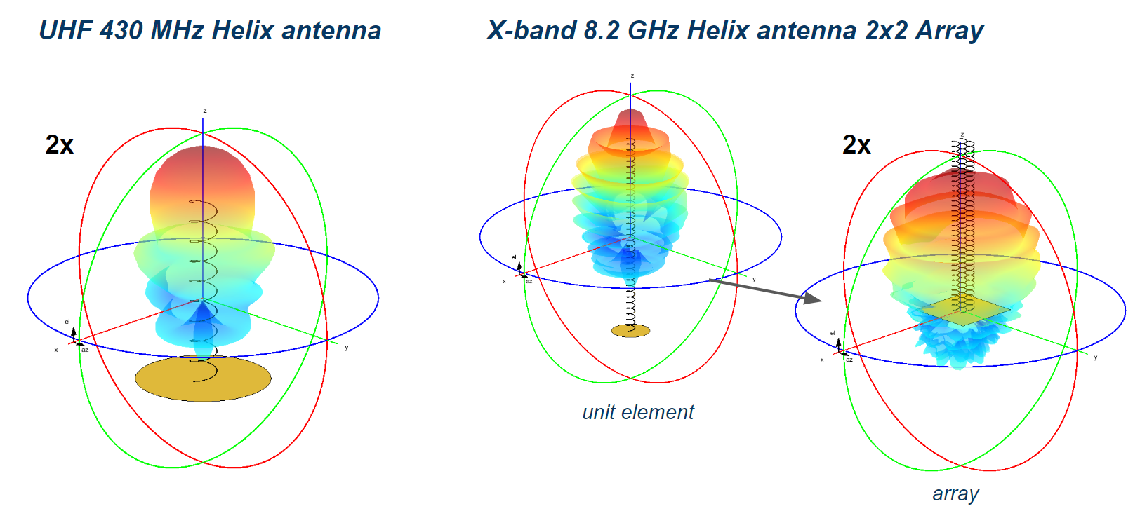
Antenna design and radiation pattern simulation
¶ Link budget for the X-band system
Starting with the Free Space Path Loss (FSPL) signal attenuation, given by this formula in decibels:
Therefore, considering a frequency of 8 GHz, and a maximal distance of 420'000 km after some discussions with the trajectory analysis team accounting for some margin, the FSPL attenuation results in:
As this is X-band transmitter, only the downlink budget is considered.
The maximal transmit power is 33 dBm (50W), meaning that the module work at its maximal power consumption of 15W, and since it is negligible compared to the total power budget, is set at 33 dBm.
Then the critical receiver sensitivity is dependent on the bandwidth, the communication protocol (SNR for a specific BER) and the quality of the RF components and architecture (Noise Figure).
Note that the -174 dB comes from the where is the Boltzmann constant for a temperature of 290 K.
The typical Noise Figure is around 1 dB (1.26 dB maybe 2dB dep on RF design) for Satellite receiver. And a SNR of 3 dB was taken considering the GMSK with convolutional coding protocol at a bit error rate (BER) of .
A drawback of using high frequency for high-speed communication is the necessity to have very large Earth ground antennas with 80 dBi gain in order to fulfill the link budget. This is achieved thanks to the ESTRACK 35m diameter antenna in New Norcia (Australia) and in Cebreros (Spain).
This results with a 9 dBm link margin, which is reasonable but may drop quickly when running some tests with real hardware. So caution should be taken with this value.
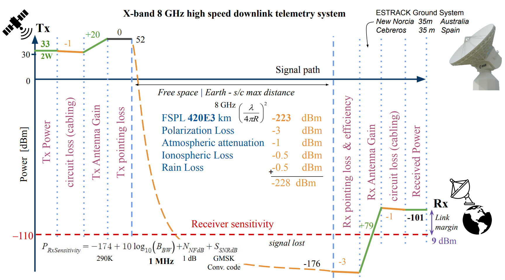
X-band 8 GHz high speed downlink system
¶ Link budget for the UHF-band system
For the UHF telecommand and telemetry system, considering also 420'000km for the distance and this time 430 MHz, it gives a free space path loss of around 25 dB less than with the X-band, illustrating here the advantage of lower frequency.
For the UHF-band, the selected Ground Segment Antenna network is KSAT Lite as it supports UHF downlink/uplink telemetry and it is sufficient considering the link budget to have lower ground antenna gain. Thus as the antenna size can be smaller, there are more antenna provided around the world for a better coverage and latency.
For the receiver sensitivity, this time it is directly given by the constructor: -115 dB dBm for 12 dB SINAD (Signal-to-Noise-And-Distortion Ratio).
Therefore the transmitted power from the ground station can be set to 40 dBm (10W) which is reasonable considering the regulations.
Note that the downlink UHF link budget is similar but with a satellite transmit power of 33dBm.
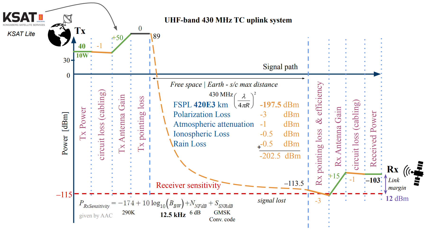
UHF-band 430 MHz Telecommand uplink system
¶ CDHS budgets
Considering all the components of the CDHS and Telecom subsystem, the total mass budget results in around 22 kg as shown below. Note that 5% margin has been applied for COTS components and 20% for helix antennas.
Finally, a large amount of mass is accounted for the harness and cabling management as it is always underestimated in space missions.
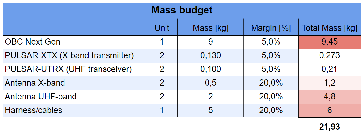
Mass budget
Looking at the power budget, it was decided to do it only for the worst-case scenario, i.e. peak power of the OBC and of the two RF modules given by their respective datasheets, as the total required power is only a small part of the full spacecraft power requirement.
Note that only one of the two redundant pairs of telemetry systems will be active as one of the two will always point away from Earth due to their configuration.

Power budget
Finally considering the thermal requirement that CDHS gives for the Thermal control system, after reading the on-board computer and RF components datasheet specifications, results with some small margin to an operational temperature range of -25°C to 60°C.
| Component | Min Temperature | Max Temperature |
|---|---|---|
| UHF and X-band RF module | -25°C | 61°C |
| On-board Computer | -30°C | 70°C |
¶ Components Datasheet
¶ Power
Power Subsystem Requirements:
Preliminary Requirements:
- The equipment shall be designed based on the total power budget of the mothercraft.
- The mothercraft’s power system must generate sufficient power to operate the systems (In all modes and phases according to their specific power needs).
- The solar panels shall cover the power needs of the mothercraft during sunlight.
- The solar panels shall recharge the batteries during sunlight.
- The batteries shall cover the power needs of the mothercraft during eclipse.
Identified Requirements:
- The batteries shall not exceed a depth of discharge of 20%.
- The power subsystem’s mass shall not exceed 300 kg (without margin)
- The solar array area shall not exceed 15 m^2 (without margin)
- The total power consumption shall not exceed 4 kW (without margin)
- The harness mass shall not exceed 30% of the total subsystem mass
Trade Offs:
Different trade offs have to be considered, which may limit the performance of the power subsystem.
- Mass vs. Redundancy: Batteries
Batteries have higher masses according to their capacity. The allocated mass for the power subsystem is limited and in the specific case of this mission it is even more limited due to the mass of the Lunar Pathfinders being fixed. Therefore, the selection of the batteries is highly dependent on this factor while also taking into account that the batteries must power the mothercraft during eclipse. - Mass vs. Redundancy: Solar Array
Solar arrays must be deployed to power the mothercraft’s subsystems in sunlight, this deployment mechanism has a weight that might have a significant impact on the mass budget. Therefore the dimensions of the solar arrays must be selected taking this into consideration. - Cost vs. Efficiency: Solar Panels
Solar panels have low efficiencies (commercial ones don’t have efficiencies above 30%). Solar panels that fulfill the power requirements need an efficiency as high as possible, which means they are expensive. It needs to be decided whether the cost is worth the efficiency depending on the client’s budget. - Performance vs. Reliability: Eclipse
For a power subsystem based on solar energy, eclipses are the most critical part. The worst case for this mission is an eclipse duration of 8.16h. During this time, the spacecraft runs entirely on the batteries. This means that the performance of the spacecraft may be limited, i.e. some actions can’t be performed during eclipse.
Justifications:
It is being considered that the solar panels will be able to cover the power needs of the mothercraft during sunlight while also being able to generate enough for recharging the batteries. These requirements were used for selecting the solar cells.
The difference between eclipse and daylight are only considered in the nominal mode.
One orbit around the Moon takes eleven hours and in the worst case scenario, of which 8.17 hours are spent in the shadow.
Based on the chosen PCDU, the power transfer efficiencies for the solar panels and the batteries can be considered as 96.5% and 94.0%, respectively.
The mission takes place over 26-27 days.dept
The mass density of the solar panels is considered to be 3.5 kg/m^2 based on commercial products including a margin.
The Depth of Discharge of the batteries is considered to be 16%.
Assumptions:
- Mean solar irradiance at the Moon: 1’361 W/m^2
- Average albedo of the Moon: 7%
- Inherent degradation of solar arrays: 77%
- Efficiency of solar arrays: 28%
- Yearly degradation factor of solar arrays: 2.75%
- Angle of incidence: 0° w.r.t. the solar cell surface
- Required standby power of one Lunar Pathfinder satellite: 25 W
- Lunar Pathfinders will use their own thermal system before deployment
- Lunar Pathfinders’ AOCS won’t be active before deployment
¶ EPS Hardware Components
The designed power system of the mothercraft has an estimated total mass of 241 kg (without margin).
The solar arrays provide up to 3’925.5 W during Sunlight (equipment + batteries).
The batteries can provide more than that during eclipse and can be used for short periods of time in other modes.
Main Batteries: SAFT VES16 11s16p Battery (2 Batteries)
- Li-Ion Battery
- Capacity per battery: 288 Ah
- Reference Energy: 11’264 kWh
- Battery Voltage Range: 9,7 to 45,1 V
- Weight per battery: 28,8 kg
- Dimensions per battery: 440 x 397 x 170 mm
- Operating temperature : -20 to 40°C
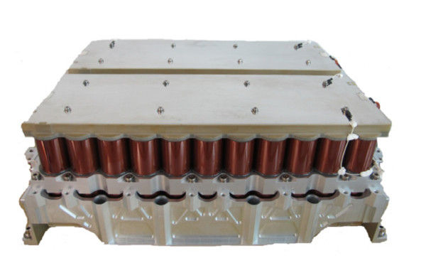
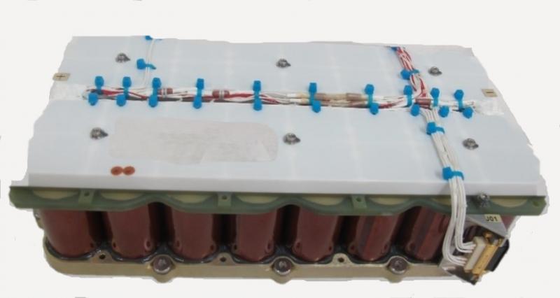
Secondary Battery for Redundancy: SAFT VES16 8s4p Battery
- Li-Ion Battery
- Capacity: 18 Ah
- Reference Energy: 512 Wh
- Battery Voltage Range: 25 to 32,8 V
- Weight: 5,80 kg
- Dimensions: 308 x 180 x 90 mm
- Operating temperature: -20 to 40°C
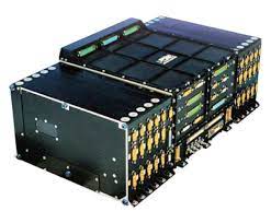
Power Conditioning and Distribution Unit (PCDU): PSR 50V MKII
- Power Handling Capacity: 11.2 kW
- Voltage Range: below 50 V
- Weight: 38.3 kg
- Dimensions: 683 x 322 x 205 mm
- Operating temperature : -35 to 70°C
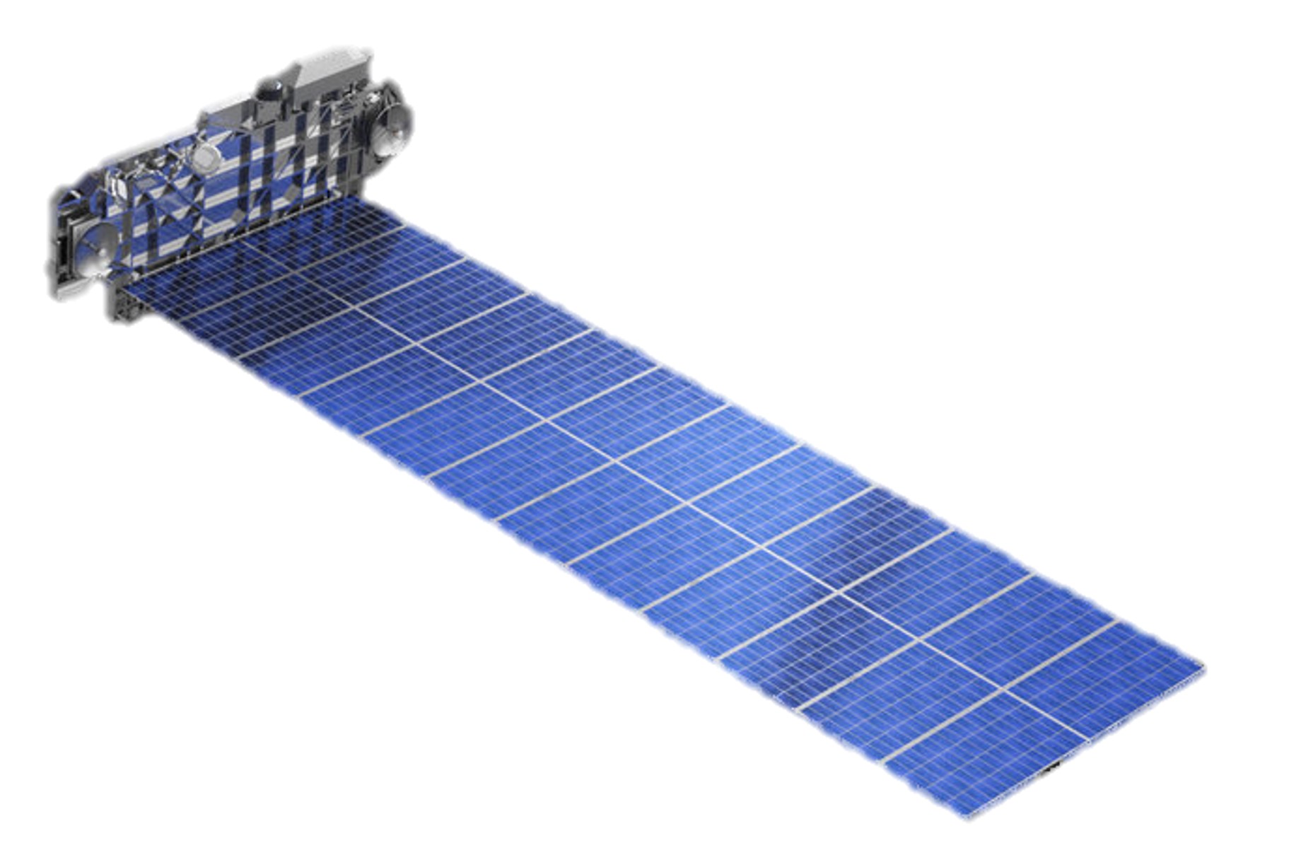
Solar Panels:
Efficiency: 28 %
Operating temperature : -70 to 100°C
Mass: 47.1065 kg
Dimensions: 13.4
Other elements: Harness
- Mass: considered to be roughly 20% of the whole subsystem mass
¶ EPS Mass Budget
| Component | Mass [kg] | Margin [%] | Mass + Margin [kg] |
|---|---|---|---|
| Solar Array | 47.107 | 5 | 49.462 |
| Solar Array Deployment Mechanism | 50 | 20 | 60 |
| Primary Battery (2x) | 57.6 | 5 | 60.48 |
| Secondary Battery | 5.8 | 5 | 6.09 |
| Harness | 42.346 | 20 | 50.815 |
| PCDU | 38.3 | 5 | 40.215 |
| Total | 241.153 | 267.062 |
¶ Power Budget
Subsystem Power Analysis
In order to size the electrical power system of the satellite, the maximum power requirements need to be known. Every subsystem provides their power requirements depending on the phase and mode, which allows finding the peak power consumption in daylight and eclipse, respectively.
In the following, the power budget is presented phase for phase. All values are in Watts (W).
- Power Budget for LEOP Mode
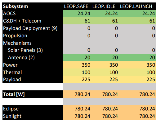
In LEOP, the power requirements are relatively low as the spacecraft is not performing any serious maneuvers yet. The main power requirements are from the thermal system, the necessary stand-by power for the payload and the power system itself.
- Power Budget for Commissioning Mode
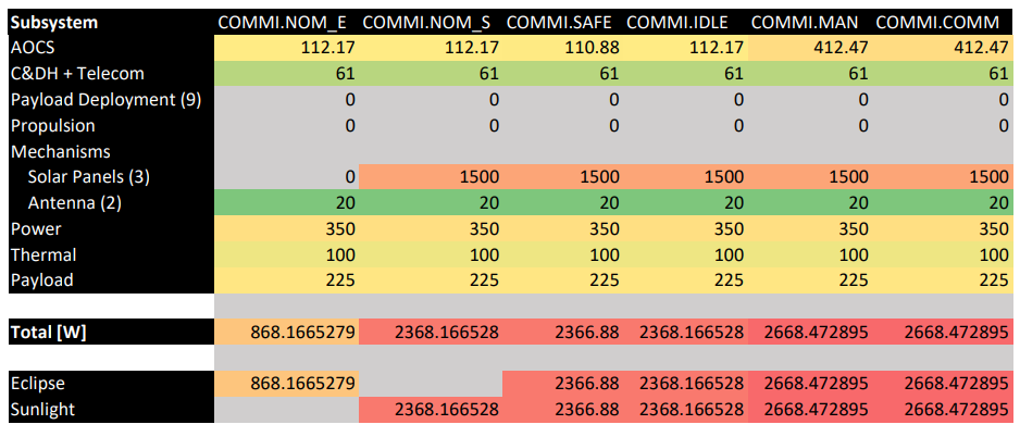
During the commissioning phase, the solar panels are deployed, which means that their drive mechanism needs to be fed from that moment on. It can be seen that it consumes a large fraction of the peak power needs in these modes, so there is a sort of trade-off between the solar panels tracking the sun, which increases the power generation and the consumption of the driving mechanism.
- Power Budget for Insertion Mode
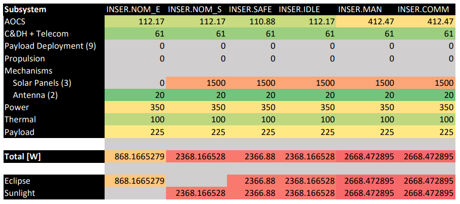
As the propulsion subsystem is handling their power needs independently, there is no increase in power demand for the insertion phase.
- Power Budget for Operation Mode
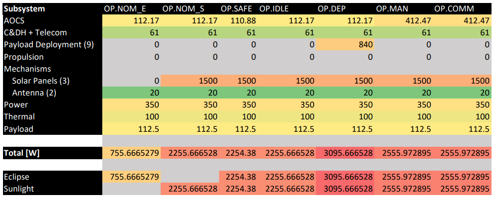
As shown in the table above, Operation Mode has the highest peak of power consumption of 3095.67 W due to the activation of the deployment mechanism of the Lunar Pathfinders. During this phase we should also take into consideration that the standby power being supplied to the payload (25 W per Lunar Pathfinder) is going to reduce each time a deployment is being made. For this power budget we considered the average power that is going to be supplied to the payload throughout this phase.
- Power Budget for EOL Mode
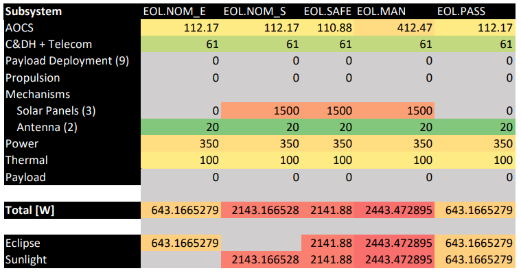
During EOL there is another peak of power consumption of 2443.47 W that is caused by the passivation techniques being used in order to avoid fragmentation/explosion of the spacecraft. These techniques will be detailed in the following section.
- General Power Budget
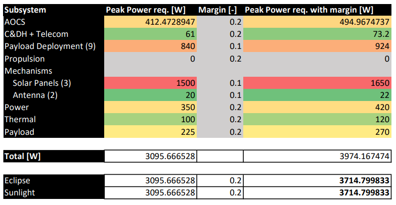
It can be seen that the solar panel tracking has the highest peak power at 1.5 kW. The second highest is for the deployment mechanism of the payload (Lunar Pathfinders), however, it’s important to note that the spacecraft will always only be in this mode for a short duration.
In fact, it’s important that this is a power budget and not an energy budget as the time spent in each mode is not taken into consideration. This is the case, because there wasn’t enough information on the time spent in the different modes to make reliable estimates.
At the bottom of the figure, the peak power requirement is determined, which has a value of ca. 3.1 kW and is in the deployment mode in the nominal phase.
To this value, a margin of 20%, because a high margin is recommended for power calculations, yielding a peak power of roughly 3.7 kW. This result is used to size the solar arrays and select the primary and secondary batteries, as well as determine what kind of PCDU (Power Conditioning and Distribution Unit) is used.
¶ Solar Array Sizing
First, the power requirement of the solar array is calculated based on the total peak power requirement during sunlight and during eclipse (including the 20% margin). The amount of time they are required, i.e. the time spent in sunlight and in eclipse , and the efficiencies of the respective power transfers and have to be taken into account.
Using the mean solar irradiance , the ideal power flux is calculated:
where is the solar panel efficiency.
For the beginning of life (BOL), the inherent degradation and the maximum angle of incidence are considered:
The life degradation factor is calculated based on the yearly degradation and the mission duration:
The power flux at the end of life (EOL) is then:
Finally, the required area can be calculated:
In this case, the calculated value is = 13.4 , which gives a solar array mass of almost 47.1 kg. This mass is calculated using common areal density values of solar arrays, in this case it’s 3.5 . Adding a 5% margin, it’s 49.5 kg. The deployment mechanism is estimated to be 50 kg, to which a 20% margin is added.
The mass of the complete solar array system, including the margins, is then 109.46kg.
| Symbol | Description | Value |
|---|---|---|
| J_s | Solar irradiance at Moon | 1361 |
| eta | Approx. efficiency of solar panels | 28% |
| I_ | Inherent degradation of solar panels | 77 % |
| \theta_ | Highest solar incidence angle | 0 rad |
| F_ | Yearly degradation factor | 2.75 % |
| N_ | Years until EOL is reached | 0.072 yr |
| T_ | Spacecraft orbit in hours | 11 h |
| P_ | Required peak power in sunlight | 4498.08 W |
| t_ | Sunlight time in hours | 2.83 h |
| qi_ | Efficiency of the power transfer for sunlight | 96.5 % |
| P_ | Required peak power in eclipse | 4498.08 W |
| t_ | Eclipse time in hours | 8.16 h |
| qi_ | Efficiency of the power transfer for eclipse | 94 % |
Passivation Strategy:
In the past, passivation has not been a primary concern when designing spacecrafts, which led to unwanted debris in space. In order to avoid fragmentation or explosion of the spacecraft after at EOL, the spacecraft needs to be passivated. This is especially important for the power subsystem.
The idea is to disconnect the batteries using a by-pass switch and use a depletion resistor. The battery should be discharged up to its minimal operational voltage (close to 0% state of charge).
The solar arrays will be disconnected by relays and short-circuited via diodes.
Results:
The power budget is used to calculate the peak power used for every mode the spacecraft can be in. The analysis reveals that this mode is the deployment of the payload in the operational phase. The total peak power requirement of the spacecraft is 3’065.67 W without margin in that mode. This value (including a 20% margin) is used to size the solar arrays.
The spacecraft requires a total solar array area of no less than 13.4 considering solar cells with a 28% efficiency. Additionally, the solar panel mass is calculated and a deployment mechanism selected.
Based on the power needs, the energy storage components are selected, i.e. the primary and secondary batteries. In this case, those are two 11’264 kWh and one 512 Wh Li-Ion batteries, respectively. A depth of discharge of 16% is used, which covers the power demands in eclipse.
An appropriate PCDU is chosen, which has a power handling capacity of 11,2 kW and supports bus voltages up to 50 V.
¶ Thermal
Requirements:
- Shall identify operating temperature range for main equipment of each subsystem
- Shall identify critical components for thermal system
- Shall compute the thermal balance of the spacecraft & solar panels
- Shall define thermal equipment ensuring acceptable temperature range of the components of the spacecraft during solar & eclipse phases
- Shall help configuration with the placement of equipment with difficult thermal requirement
Assumptions:
- Pathfinders are designed for the space environment encountered.
- Operating temperatures given by datasheets are the acceptable surface temperatures of the components.
- 20% of power budget is converted into heat (internal power dissipation).
- Infrared heating arriving on the spacecraft from Earth is negligible compared to Moon’s.
- According to other missions in Moon orbits, eclipse duration was much lower (about 120 minutes) than our preliminary calculations (about 400 mins). As the minimum reached temperature is highly dependent (ESA calculations sheets) and could not determine with trajectory an accurate value of its duration within the 2 weeks sessions, this value was cut in half to make more sense for the design of the equipment.
- Internal components of the spacecraft are assumed to be at the same temperature as the external temperature of the spacecraft.
Trade-offs:
- Thermal control strategies : active versus passive
- Level of modeling (computations / scale / interfaces / configurations)
- Global (spacecraft) versus local (batteries) dimensioning
- Maintain all elements in their operation temperature range during solar and eclipse phases (eg. MLI thickness for batteries)
Justifications
¶ Operating temperature ranges
Temperature ranges were determined by consulting other subsystems to identify their main components with temperature requirements.
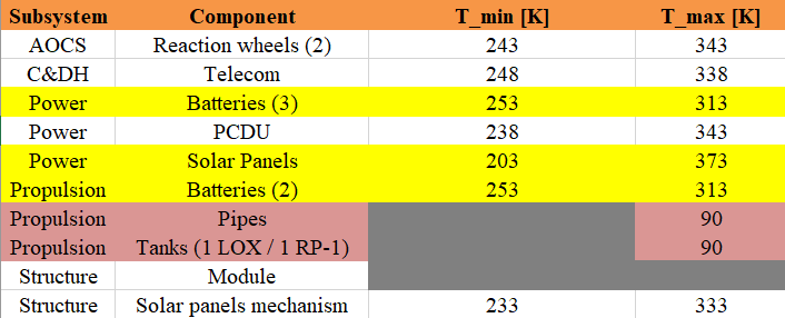
Most restrictive components (highlighted in yellow) are batteries and solar panels. Batteries are inside the spacecraft whose thermal problem will be addressed first while solar panels temperature determination is independent of the internal structure of the spacecraft.
Pipes and tanks are highlighted in red as they are the most restrictive components overall, but were tackled specifically and together with the propulsion subsystem.
Apart from these two components, the internal operating temperature range of the spacecraft is from -20 [°C] to 40 [°C] and is imposed by the batteries of power and propulsion subsystems.
¶ Thermal balance
All the details on the equations and calculations can be found in Space Mission Engineering: The New SMAD, pp.444-448, small version. Most of these equations are implemented in the provided ESA datasheet which was used to perform most of the calculations.
¶ Spacecraft
One models the thermal balance of the spacecraft with the following equilibrium
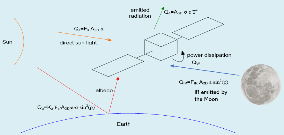
Where
- [W] is the heat emitted by radiation of the spacecraft
- [W] is the heat received from the Sun
- [W] is the solar heat received from the reflection on Earth
- [W] is the infrared heating from the Moon
- [W] is the internal power dissipation of the spacecraft
From this model, one can compute the equilibrium temperature of the spacecraft using the following values from our mission design:
Albedo factor (Moon) : 0.07 [-]
Maximum IR heating (Moon) : 1255 [W/m]
Spacecraft external structure is made of Aluminum 6061 (from Structure and Mechanisms)
340 [W] 800 [W] (from Power)
Maximum eclipse duration : 200 [min] (from Trajectory and assumptions)
¶ Solar panels
Temperature range of the solar panels were determined with the ESA thermal calculations sheet using the parameters provided from Power subsystem for their solar panels design.
¶ Thermal equipment and sizing
Passive - Multi-layer insulation (coating)
According to the upper and lower temperature limit of the spacecraft, one started by looking at thermal passive equipment: multi-layer insulation (MLI). It is the most common solution applied to spacecraft as it is thin and easy to implement.
ESA thermal calculations sheet allows to apply a coating to the external surface in the model (change in absorptivity and emissivity)
Our MLI was designed to obtain the closest temperature range fulfilling the temperature requirements of all internal components. Furthermore, it was assumed it would be preferable to guarantee the [°C] requirement first, as it seems easier in terms of volume, mass and costs to apply heating patches/wires than designing a cooling system for many components.
In addition, MLI was selected, alongside with heating patches, to protect the batteries. It was designed (using thermal resistance concept from heat transfer such that it guarantees -20 [°C] on the batteries during eclipse alongside with the heating patches and that the upper limit temperature of batteries is not exceeded during solar phase.
Active - Heating patches
During eclipse time, it is necessary to heat the batteries. For this purpose, one will use wires and patches. To maintain a temperature of -20 [°C], it was determined - from the estimated heat flux by conduction of the batteries through its insulation - that about 100 [cm] of these patches were necessary.
Active - Radiator
Even though at first sight, one does not need a radiator as the maximum temperature of the spacecraft is compliant with the requirements, for extra safety, one designs a radiator in the case of max power dissipation and assuming no external heat inputs using (11-23) of the SMAD (provided in the ESA calculations sheet). Area of the radiator is found as follows
One determined a radiator of about 1.8 [m] would be necessary and assumed from this ESA radiator description, that it dissipates about 100 [W/m] (lower bound).
Results:
Thermal balance and critical components
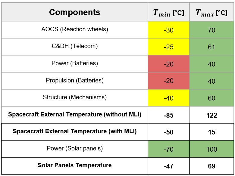
Thermal equipment
- Passive - Multi-layer insulation : aluminized kapton 1 mil : 25 [kg] for spacecraft modules, batteries (10mm thickness), solar panels mechanism and propulsion interfaces
- Active - Heating patches : 2 [kg] composed of 100 [cm] of patches and accounting for thermostats, sensors and other electronics, used during eclipse on the batteries, consumes 100 [W] and provides 86.7 [W]
- Active - Radiator 18 [kg], 1.8 [m$^2] can dissipate up to 180 [W]
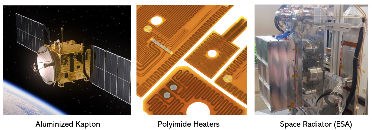
¶ Systems Engineering and Budgets (system level)
¶ Requirements
- Shall support the other disciplines with their design
- Facilitate communication with the different subsystems
- Shall create a system mass budget, check assumptions and consistency of the subsystems
¶ Tradeoffs
- Number of Pathfinder satellites to be deployed : [6 to 9].
¶ Justifications
As stated in the introduction of this study, the number of pathfinder satellites was the main design driver of our mission.
On the one hand, more satellites would mean less room and less available mass for our deployer subsystems within the A64 fairing. This also leads to less propellant, and therefore reduced mission capabilities.
On the other hand, with more satellites also comes more coverage of the Moon surface for communication and navigation purposes, which is the key requirement of the customer. Since at least 4 visible satellites are needed to allow for precise positioning, this was considered as the bare minimum for our mission.
Subsequently, the discussions between the systems engineers and the design team as well as the iterative loops allowed the systems engineering team to find the optimal number of pathfinders that would lead to a successful completion of the mission until its end of life.
¶ Computation
a. Subsystem distribution
The allocation of mass budgets between the deployer's subsystems was based on the Space Mission Analysis and Design (SMAD) book:
| Subsystem | Distribution [%] |
|---|---|
| Thermal | 3 |
| Payload | 11 |
| Power | 19 |
| Propulsion | 13 |
| Configuration | 7 |
| Structure and mechanisms | 26 |
| CDHS | 12 |
| AOCS | 9 |
In our case, as the payload mass changed over the course of the study, and since it was the main driver of our mission, the mass distribution was modified to take such variations into consideration.
First, from the total system dry mass was computed the portion of the payload (fixed by the number of satellites). Then, this portion was used to recompute the distributions of the other subsystems according to the following formula :
With:
- the adapted mass distribution for a specific subsystem
- the initial mass distribution of a specific subsystem as per the SMAD book
- the computed mass distribution of the payload within the total dry mass of the system
- the initial mass distribution of the payload as per the SMAD book : 11 %
b. Margins philosophy
Once computed, these distributions allowed us to define the mass budgets of the subsystems, taking into consideration some safety margins. Indeed, these margins were needed to better account for uncertainties in the design. Here, two kinds of margins were used:
- Components margins : at the level of the subsystems
- Subsystems margins : at the level of the overall system
According to [ESA’s Margin Philosophy] (https://sci.esa.int/documents/34375/36249/1567260131067-Margin_philosophy_for_science_assessment_studies_1.3.pdf), the margins to be applied at equipment level shall comply with the following requirements:
- R-M2-41 : ≥ 5 % for “Off-The-Shelf” items
- R-M2-42 : ≥ 10 % for “Off-The-Shelf” items requiring minor modifications
- R-M1-43 : ≥ 20 % for new designed / developed items, or items requiring major modifications or re-design
These margins were applied by each team to their components before sharing the total mass of their subsystem to the systems engineering team. Then again, a system level margin was added to the subsystem masses, according to requirement R-M1-1 :
“The total dry mass at launch of the spacecraft shall include an ESA system level mass margin of 20 % of the nominal dry mass at launch”.
Therefore, a 20 % margin was applied by the systems engineers on top of the subsystems’ total masses. As the pathfinder satellites making the payload were already space-qualified, a 5% margin was used.
Finally, once added together, the subsystem masses and their margins made the system total dry mass. By adding the propellant mass, also including a component margin for maneuver uncertainties, we could compute the system total wet mass.
c. Budget update
To ensure that this final wet mass value is within the performance of the A64 launcher, an iterative process was used to keep track of the subsystem mass budgets after each iteration :
- Compute Ariane 64 total payload mass without adapter: 8500 kg (fixed)
- Update propellant mass to complete full mission (from propulsion team)
- Compute system dry mass (by removing the propellant mass from Ariane 64 performance)
- Define the total number of satellites for this iteration
- Adapt the subsystems’ mass distribution coefficients (based on Equation XXX)
- Compute the allocated mass per subsystems (by applying the mass distribution coefficients to the system dry mass).
- Compute target masses per subsystems by removing the 20% system level margin to each allocated subsystem mass
- Compare target masses with actual subsystem masses (provided by the design teams).
- Decide upon design change based on margins left
In case of exceeded margins, some criteria may help reduce the gap :
- Refine components margins
- Change number of payload satellites
- Reduce propellant required by reviewing mission conops
¶ Evolution
The evolution of the mass budget over the 2 weeks is presented below.
.png)
As observed in this graph, 9 iterations were completed during this study. Starting with 6 satellites, we quickly moved to 9 pathfinders within our payload. The system level margins, first unaccounted for, were then added by iteration 4. From that point, our goal has been to try and reduce the gap between our actual wet mass and the A64 performance following the strategy mentioned in the previous section.
¶ Results
The final mass budget of the mission is detailed below:
| Subsystem | Mass [kg] | Margin [%] | Mass w/ margin |
|---|---|---|---|
| Thermal | 37 | 20 | 44.4 |
| Payload | 2970 | 5 | 3118.5 |
| Power | 267.06 | 20 | 320.47 |
| Propulsion | 306.85 | 20 | 362.22 |
| Structure and mechanisms | 578.56 | 20 | 694.27 |
| CDHS | 22 | 20 | 26.4 |
| AOCS | 133.77 | 20 | 160.52 |
| Configuration | 120.82 | 20 | 144.99 |
| Deployer dry mass w/ margins [kg] | 4877.78 |
|---|---|
| W/o margin [kg] | 4436.06 |
| Propellant mass w/ 5% margin [kg] | 3587 |
|---|---|
| W/o margin [kg] | 3416.2 |
| Deployer wet mass w/ margin [kg] | 8464.78 |
|---|
| Adapter mass [kg] | 100 |
|---|
| Total launch mass [kg] | 8564.78 |
|---|
With a total mass of 8564.78 kg, our mission is within the performance of 8600 kg of the Ariane 64 launcher! The mission is therefore feasible, and further studies can be conducted to refine this concept.
¶ Risk Assessment
The risk assessment is an important step in the mission design process as it helps to identify potential risks and their consequences, prioritize mitigation strategies, and inform decision-making. By assessing and prioritizing risks, mission designers can make informed decisions on how to allocate resources and focus on key areas of risk mitigation.
Probability is usually measured on a scale of 1 to 5, with 1 being the lowest probability and 5 being the highest. Severity is also measured on a scale of 1 to 5, with 1 being the least severe and 5 being the most severe.
Once the probability and severity of a risk have been determined, they are multiplied together to calculate the risk level as shown on the figure below. This is expressed as a number and a color-coded system, such as light green for very low risk, green for low risk, yellow for moderate risk, orange for high risk and red for very high risk.
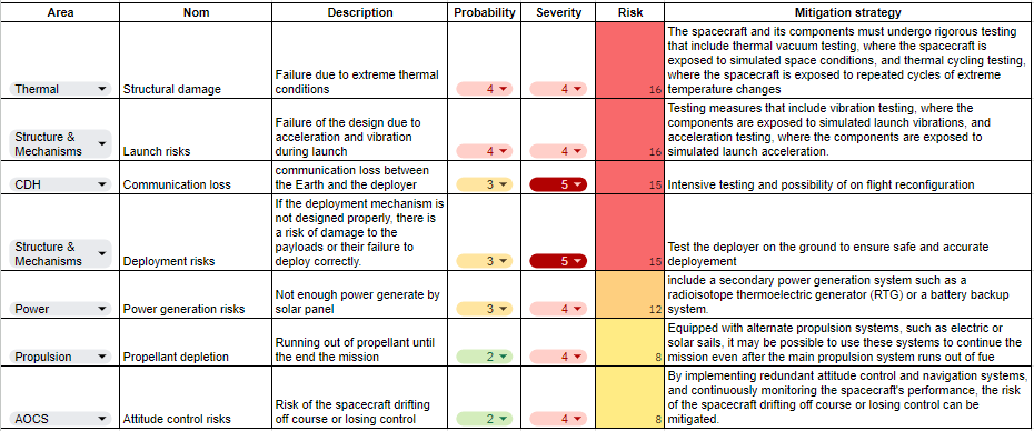
This is the legend of the severity matrix :
- 1-2 : Very Low Risk
- 3-4 : Low Risk
- 5-6-8 : Medium Risk
- 9-10-12 : High Risk
- 15-16-20 -25 : Very High Risk
By identifying the highest-risk scenarios, one can take proactive measures to mitigate those risks and prevent potential disasters.

¶ Costs
Although costs beyond the scope of this study will need to be calculated as part of a follow-up analysis, the team does not currently have a dedicated cost manager. Start-up costs are estimated at 91 million Euros and must take into account the machining processes and components used in all other subsystems.
¶ Lessons Learned
¶ Trajectory Analysis
- We gained insights into the various tradeoffs that must be considered when performing a trajectory analysis. These tradeoffs may include factors such as propellant mass or evaporation, time constraints, and the overall mission objective.
- During our trajectory analysis, we found that learning how to use the NASA software GMAT was crucial for achieving accurate results. By using GMAT, we were able to simulate and verify many of our calculations, which helped to increase our confidence in the trajectory analysis.
¶ Configuration
- Not having any particular knowledge I was able to learn on the field the role of the configuration engineer
- My first step was to learn the course of a mission and find information in the documentation
- Then with Structures and Mechanisms we fixed a preliminary plan for the global structure of spacecraft
- Then I looked at each subsystem to see what hardware was used and what the different specifications were for each, I understood all links between all subsystems, all the needs of each subsystem to the other subsystems.
- Finally, we made the final configuration of the spacecraft. Of course, this configuration is not very precise and is probably not the final configuration, but it allows us to realize how the subsystems are managed and allows us to represent the spacecraft.
- I was able to have an overview and to know roughly what each subsystem was doing during the mission, and my task was to connect each subsystem between them.
¶ Structures and Mechanisms
- The inertia of the structure has a very strong impact on AOCS and this interface should not be neglected as it can have a large impact on the control mechanisms and on the overall spacecraft’s mass
- A preliminary plan of the accommodation of the subsystems should be done with configuration early. Some systems have specific requirements, like placing control systems on the center of mass or having antennas facing each other. We chose a 3 symmetric structure and it led to integration issues that could luckily be resolved.
- It is difficult to do valid preliminary calculations on the experienced flight loads, so the primary goal should be the overall system’s integration and the structure’s mass.
- Make a clear list of the other subsystems’ needs for mechanism. There are a lot of COTS mechanisms available but with very specific specifications. It is difficult to choose from Structure’s point of view only.
¶ Propulsion
- The solution required wasn’t standard with the trajectory given and the high mass of the payload: green, high thrust, cheap, light, efficient. We learned to compromise between these and lower our mission expectancies maybe not even enough in the end.
- We learnt to adapt as info and problems were coming one after every solution we found for the precedent: first the propellant and green engines TRL, then the mass of regular cryogenic engines, the power consumption of our system, then the evaporation and storing of cryogenic propellant and eventually the reignitability problem. It was difficult to choose a good propulsion system. Maybe we should have spent more time on a different trajectory.
- Do not neglect some standard propulsion issues that will have a big impact on other subsystems later on and are difficult to change: reignitable? Storable? Shape of tanks ? Burn times ? Maybe do a list of the most critical aspects not to neglect before choosing an engine for a certain mission.
- The computations are easy for this subsystem so focus maybe more on integration in the frame of the mission, compatibility with other subsystems.
¶ AOCS
- Do not only consider the orbit maintenance feature of AOCS to size the subsystem, but also the time and energy it requires to steer the S/C for a major manoeuvre.
- Make sure the trajectory and mission conops are well-defined to estimate how many slew manoeuvres will be required before sizing the system.
- AOCS is a subsystem which requires a substantial amount of power.
- It is more efficient in terms of subsystem life-time and mass to use reaction wheels instead of thrusters.
- Make sure all actuator/sensor interfaces are compatible with CDHS’ main computer.
-
¶ CDHS
- Better understand how the link budget works and how each design element impacts that budget, such as the modulation or protocol used, or whether a coding method improves the SNR for a specific BER.
- Also making a drawing of the link budget helps for human communication and to check for potential errors, e.g. defining Loss = -10dB and then subtracting the loss in the link budget equation, resulting in a magical 20 dB gain...
- It is important to ensure that the RF equipment and used protocols are compatible with the ground station network, as well as how it is coordinated with the other customers. It goes as well for radio regulation (FCC & ITU).
- Antenna design is critical: Tuning the antenna performance to meet the mission requirements enables to increase the range by minimizing the power consumption of the communication subsystem.
- Keeping margin everywhere is crucial as usually the most unknowns come when you are ground testing your design with real hardware and integration.
- Do not forget to consider the space environment encountered during all mission phases, and study how it can affect the electronic & radio systems.
¶ Power
- The solar array shall be designed so it has enough surface to provide power to the mothercraft’s subsystems while orbiting the Moon during sunlight and to recharge the batteries during eclipse while taking into consideration their impact in the mass due to the deployment mechanism.
- Other subsystems must define their own power budget considering which components will be active or inactive during each phase of the mission.
- To estimate the standby power that our spacecraft is going to supply to the payload we must consider the active subsystems that the payload will use during transfer.
- In the future, an energy budget should be created in addition to the power budget.
- It’s important to put as many parameters on COMET as possible (such as maximum and minimum power consumption for the thermal subsystem in this case).
¶ Thermal
- Minimum temperature of the spacecraft is highly dependent on the eclipse duration and is not easy to obtain, more work with the trajectory subsystem should be done to obtain an accurate value.
- It is difficult to develop a thermal model to design internal components by “small” calculations that does not seem too rough/unrewarding as it is too dependent on the configuration of everything. Thus, at this stage, exploit everything possible explained in the book Space Mission Engineering: The New SMAD.
- Try to identify earlier on which quantities the thermal subsystem connects to other subsystems to obtain a better COMET network over the iterations.
- ESA calculations sheet is a very useful tool (more of it could have been exploited) and equations/models are heavily linked to Space Mission Engineering: The New SMAD. (Tip: use “update all graphs” to update all the values, many are hidden in blue columns and need to be refreshed when you change eclipse duration for example)
¶ Systems Engineering
- Take into account margins at the subsystem level based on the level of confidence of the design.
- Add an extra margin of 20% at the system level on the total dry mass budget.
- Keep track of the budgets (mass, power, volume) as the project progresses.
- Define a threshold based on the project's requirements and objectives and once the budget changes fall below the defined threshold, it can be assumed that the margins cover the uncertainties and the budget can be finalized.
¶ Glossary
AOCS[acr.] : Attitude Orbit Control System
A64[acr.] : Ariane 64
BOL[acr.] : Beginning Of Life
COTS[acr.] : Commercial Off-The-Shelf
DoD[acr.] : Depth of Discharge
EOL[acr.] : End Of Life
EPS[acr.] : Electrical Power System
Lunar Pathfinder[acr.] : Lunar Pathfinder satellite will provide communications services around the Moon.
LEOP[acr.] : Launch and Early Operations
OBC[acr.] : On-Board Computer
PCDU[acr.] : Power Conditioning and Distribution Unit
RAAN[acr.] : Right Ascension of the Ascending Node
SMAD[acr.] : Space Mission Analysis and Design
SNR[acr.] : Signal to Noise Ratio
TLI[acr.] : Trans Lunar Injection
¶ Appendix
¶ Scripts
¶ Trajectory calculations
Code book can be found here.
import numpy as np

# Parameters
# ---Earth-----
r_earth = 6378.0 # km
mu_earth = 398600.0 # km^3/s^2
# ---Moon------
r_moon = 1737.0 # km
mu_moon = 4902.8 # km^3/s^2
moon_vel = 1.022 # km/s

# ---Misceallaneous---
lowMargin = 1.05 # %
bigMargin = 2.00 # %
nbr_sat = 9 # Number of satellites
mission_time = 0.0 # s

# first elliptical orbit around the Earth reach with the Ariane 64
apogee = 400000.0+r_earth # km
perigee = 230.0+r_earth # km

print("Apogee: ", apogee, "km")
print("Perigee: ", perigee, "km")

a1 = (apogee+perigee)/2
print("Semi-major axis: ", a1, "km")

# Calculate the eccentricity
e1 = (apogee-perigee)/(apogee+perigee)
print("Eccentricity: ", e1)

v_apogee = np.sqrt(mu_earth*(2/apogee-1/a1))

# Arrival speed at the Moon SOI
v_arrival_inf = v_apogee - moon_vel
print("Arrival speed at the Moon SOI: ", v_arrival_inf, "km/s")

# Second elliptical orbit around the Moon
aposelene = 7331+r_moon # km
periselene = 673+r_moon # km
print("Aposelene: ", aposelene, "km")
print("Periselene: ", periselene, "km")


inclination = 54 # deg
a_sat = (aposelene+periselene)/2

# Velocity at periselene
v_p = np.sqrt(v_arrival_inf**2 + 2*mu_moon/periselene)

# Velocity at periselene for the wanted orbit
v_periselene = np.sqrt(mu_moon*(2/periselene-1/a_sat))

# Delta V
delta_v = v_p - v_periselene

print('Delta V =', delta_v, 'km/s')
print('The deployer is now in orbit around the Moon')
#print('vp =', v_p, 'km/s')
#print('v_periselene =', v_periselene, 'km/s')

Delta V = 0.39400238977396973 km/s
The deployer is now in orbit around the Moon

# Deployement phase 1
# -------------------
T_sat = 2*np.pi*np.sqrt(a_sat**3/mu_moon) # s
print('Period =', T_sat/3600, 'h', 'for the satellite orbit')

apogee_dec = 250 # km
a_catch_up = a_sat - apogee_dec/2 # km
print('Semi-major axis for the catch up orbit =', a_catch_up, 'km', '\n')

deltaX = 3*np.pi*(a_sat - a_catch_up) # km
print('Delta X =', deltaX, 'km, each orbit')

deltaV_depl = np.sqrt(mu_moon*(2/periselene-1/a_catch_up)) - np.sqrt(mu_moon*(2/periselene-1/a_sat))
print('Delta V =', deltaV_depl, 'km/s, for the deployement phase 1', '\n')

# for 9 satellites deployed : 5 satellites on the first orbit, 4 satellites on the second orbit
nbr_sat_first_orbit = 5
nbr_sat_second_orbit = 4

nbr_dv_first_deploy = 2*(nbr_sat_first_orbit-1)
nbr_dv_second_deploy = 2*(nbr_sat_second_orbit-1)
deltaV_depl_tot = (nbr_dv_first_deploy+nbr_dv_second_deploy)*abs(deltaV_depl)

# Number of orbits between two deployement (on the lower orbit) : N*T_catch_up = N*T_sat - T_sat/nbr_sat
T_catch_up = 2*np.pi*np.sqrt(a_catch_up**3/mu_moon) # s
N_orbits1 = (1/5)/(1-T_catch_up/T_sat)
N_orbits2 = (1/4)/(1-T_catch_up/T_sat)

print('Number of orbits needed on the first catch up orbit =', np.round(N_orbits1), '(rounded from', N_orbits1, ')')
N_orbits1 = np.round(N_orbits1)
t_wait_between_realesed1 = N_orbits1*T_catch_up # s
print('Waiting time between deployement on the first orbit =', t_wait_between_realesed1/3600, 'h =', t_wait_between_realesed1/86400, 'days','\n')

print('Number of orbits needed on the second catch up orbit =', np.round(N_orbits2), '(rounded from', N_orbits2, ')')
N_orbits2 = np.round(N_orbits2)
t_wait_between_realesed2 = N_orbits2*T_catch_up # s
print('Waiting time between deployement on the second orbit =', t_wait_between_realesed2/3600, 'h =', t_wait_between_realesed2/86400, 'days','\n')

# Total waiting time
print('Duration of the first deployment phase :',t_wait_between_realesed1*(nbr_sat_first_orbit-1)/86400, 'days')
print('Duration of the second deployment phase :',t_wait_between_realesed2*(nbr_sat_second_orbit-1)/86400, 'days')
t_waiting = t_wait_between_realesed1*(nbr_sat_first_orbit-1) + t_wait_between_realesed2*(nbr_sat_second_orbit-1) # s
print('Total waiting time =', t_waiting/3600, 'h =', t_waiting/86400, 'days')
print('Delta V total for deployement =', deltaV_depl_tot, 'km/s','\n')

#End of life :
# -------------
a_eoli = a_sat + 50/2 # km
a_eolf = a_eoli + 50/2 # km
deltaV_eol1 = np.sqrt(mu_moon*(2/periselene-1/a_eoli)) - np.sqrt(mu_moon*(2/periselene-1/a_sat))
deltaV_eol2 = deltaV_eol1 + np.sqrt(mu_moon*(2/(aposelene+10)-1/a_eolf)) - np.sqrt(mu_moon*(2/(aposelene+10)-1/a_eoli))

deltaV_eol = (abs(deltaV_eol1) + abs(deltaV_eol2))
print('Delta V for end of life =', deltaV_eol, 'km/s')

# summary
# -------
dV_moon = delta_v*lowMargin
dV_incl = 1.029*lowMargin
dV_depl = deltaV_depl_tot*lowMargin
dV_eol = deltaV_eol*lowMargin

print('Delta V for Moon SOI =', dV_moon, 'km/s')
print('Delta V for inclination =', dV_incl, 'km/s')
print('Delta V for deployement =', dV_depl, 'km/s')
print('Delta V for end of life =', dV_eol, 'km/s')

#compute the total delta V
dV_tot = abs(dV_moon) + abs(dV_incl) + abs(dV_depl) + abs(dV_eol)
print('Total Delta V =', dV_tot, 'km/s')

# Compute the time of flight
# --------------------------

# Arianne 64
TA64 = np.pi*np.sqrt(a1**3/mu_earth)
print('Time with Ariane 64 =', TA64/86400, 'days')

T_depl = t_waiting

# End of life T/2 between the two burn
T_eol = np.pi*np.sqrt(a_eoli**3/mu_moon)/2
print('Time of flight for the end of life =', T_eol/86400, 'days')

T_mission = TA64 + T_depl + T_eol
print('Total time of flight =', T_mission/86400, 'days')

# Total time of flight after the separation with the Ariane 64
T_deployer = T_depl + T_eol
print('Time of flight after separation with A64 =', T_deployer/86400, 'days')

## Timeline
# ----------
mission_time = 0
mission_time += TA64
print('LOI and first satellites', np.round(mission_time), 's', ' =', np.round(mission_time/86400,2), 'days')
for i in range(nbr_sat_first_orbit-1):
    mission_time += t_wait_between_realesed1
    print('Deployement on first orbit, satellites n°', i+2,':', np.round(mission_time), 's', ' =', np.round(mission_time/86400,2), 'days')
print('\n')
print('Change of inclination and Deployement on second orbit, satellites n°', i+6,':', np.round(mission_time), 's', ' =', np.round(mission_time/86400,2), 'days')
for i in range(nbr_sat_second_orbit-1):
    mission_time += t_wait_between_realesed2
    print('Deployement on second orbit, satellites n°', i+7,':', np.round(mission_time), 's', ' =', np.round(mission_time/86400,2), 'days')

#EOL
mission_time += T_eol/2
print('End of life :', np.round(mission_time), 's', ' =', np.round(mission_time/86400,2), 'days')

# Ecipse orbit around the Moon
# ----------------------------
# find the time between two point of the elipse
a = 5740 # km
b = 0.58*a # km
e = np.sqrt(1-(b/a)**2)
c = a*e
T = 2*np.pi*np.sqrt(a**3/mu_moon) # s

l1 = a #the line bewteen the moon(focus) and the 'side' of the ellipse
ellipse_area = np.pi*a*b
area_covered = ellipse_area/2 - 2*c*b/2

# Time between two point of the ellipse
T_no_ecllipse = T*area_covered/ellipse_area
print('Direct sunlight =', T_no_ecllipse/3600, 'h')
print('Time of the ecllipse =', (T-T_no_ecllipse)/3600)
print('Period  =', T/3600, 'h')
¶ Propulsion calculations
Code book can be found here.
import numpy as np
import matplotlib.pyplot as plt
# This function returns the mass of the propellant USED at the end of a maneuver given an initial mass and a delta-V.
def rocket_equation(m_i, Isp, delta_v):
return m_i-m_i/np.exp(delta_v/(Isp*9.8056))
# This function returns the mass of the propellant at the end of the mission from the total delta-V with boil-off.
def boil_off_mass(bor,m_i,prop_mass_init,duration,timeline,delta_v,Isp,deployment,payload):
prop_mass = np.zeros(duration)
prop_mass[0] = prop_mass_init
for i in range(1,duration):
prop_mass[i] = prop_mass[i-1] - prop_mass[i-1]*bor
if any(i==timeline):
prop_mass[i] = prop_mass[i]-rocket_equation(m_i,Isp,delta_v[np.where(timeline==i)])
prop_mass_init = prop_mass_init - prop_mass[i]
if deployment[np.where(timeline==i)]==True:
m_i = m_i - prop_mass[i] - payload
else:
m_i = m_i - prop_mass[i]
return prop_mass
# This function computes the burn time of a maneuver given the Isp, the propellant mass needed and the thrust of the motor.
def burn_time(prop_mass, Isp,thrust):
return prop_mass*(Isp*9.8056)/thrust
#### INPUTS ####
payload = 280 #payload mass in [kg]
m_i = 8500 #initial mass in [kg]
Isp = 343 #specific impulse in [s]
bor = 0.7/100 #boil-off rate in [percent/day]
duration = 26 #duration of the mission in [days]
thrust = 26000 #thrust in [N]
#Insert the delta_v with the margins. Ideally 5%.
delta_v = np.array([1494, 78.1/7, 78.1/7, 78.1/7, 78.1/7, 78.1/7, 78.1/7, 78.1/7, 6.2]) #array containing the delta-v of each maneuver in [m/s]
deployment = np.array([True, True, True, True, True,True,True,True,False])
#Insert the time of each maneuver.
timeline = np.array([5,7,10,13,16,19,22,25,26]) #array containing the time of each maneuver in [day]. N.B. 0 is the launch day
timeline = timeline-np.ones(len(timeline)) #timeline starts from 0 and maneuvers are done at the beginning of the day.
#Comment the line directly above if you want the maneuvers to be done at the end of the day.
#### END OF INPUTS ####
prop_mass = [] # array containing the propellant mass used for each maneuver in [kg]
m = m_i
for dv,value in zip(delta_v,deployment):
prop_mass.append(rocket_equation(m, Isp, dv))
if value==True:
m = m - rocket_equation(m, Isp, dv)- payload
else:
m = m - rocket_equation(m, Isp, dv)
for prop in prop_mass:
print("The propellant mass needed for maneuver",prop_mass.index(prop)+1,"is: ", prop, "kg")
print("\nWithout boil-off, the propellant mass needed is: ", np.sum(prop_mass), "kg")
#Computing the boil-off rate
V = 2.13 #volume in m^3
rho = 1141 #density in kg/m^3 at 1bar. Usually aroung 1 and 3 bars in propellant tanks
H = 2.13e5 #enthalpy in J/kg
kappa_alu = 121 #thermal conductivity of t87-2219 aluminum alloy. https://asm.matweb.com/search/SpecificMaterial.asp?bassnum=MA2219T87
kappa_mli = 1e-5 #thermal conductivity of mli: https://iopscience.iop.org/article/10.1088/1757-899X/396/1/012061/pdf#:~:text=The%20effective%20thermal%20conductivity%20of,conduction%20modes%20of%20heat%20transfer.
delta_x_alu = 3.5e-3 #m, aluminum thickness
delta_x_mli = 0.5e-3 #m, insulation layer thickness
T_ox = 91 #boiling point of LOX at 1 bar.
T_ex = -4+273 #worst case scenario if exposed to the Sun(see thermal). Boiling point of LOX: -183.1 C, worst case temp: 15 C
delta_T = np.abs(T_ox-T_ex) #worst case scenario if exposed to the Sun(see thermal). Boiling point of LOX: -183.1 C, worst case temp: 15 C
Q = (kappa_alu*kappa_mli)/(kappa_alu*delta_x_mli + kappa_mli*delta_x_alu)*delta_T #Heat flux in W/m^2 assuming a planar for al and mli.
boil_off = Q*24*3600*10/V/rho/H*100 #boil off rate in %/day
print(Q,boil_off)
plt.figure()
for delta_T in np.array([100,125,150,175,195,210]):
Q = (kappa_alu*kappa_mli)/(kappa_alu*delta_x_mli + kappa_mli*delta_x_alu)*delta_T
boil_off = Q*24*3600*10/V/rho/H*100
plt.scatter(Q,boil_off,label = '$T_e = {:.0f}$ C'.format(delta_T-273+91))
plt.axhline(y = 0.7, color = 'r', linestyle = 'dashdot', label = '$T_e = 28$ C')
plt.xlabel(r'Heat flux $\left[\frac{W}{m^2}\right]$')
plt.ylabel(r'Boil-off rate $\left[\frac{\%}{day}\right]$')
plt.legend(loc = 'best')
plt.show()
#Let's compute with the boil-off now.
#This is the mass on which you'll iterate to find the margin you want with boil-off. It's an initial guess on the propellant mass.
prop_mass_init = 3587
prop_mass = boil_off_mass(bor,m_i,prop_mass_init,duration,timeline,delta_v, Isp,deployment,payload)
for prop in prop_mass:
print("The propellant mass at day",np.where(prop_mass==prop)[0][0]+1,"is: ",'%.2f' % prop, "kg")
print("And the margin is:", prop_mass[-1]/prop_mass_init*100,"%")
plt.figure(figsize=(15,7))
plt.plot(prop_mass,label = r'Boil-off rate = $1.05\%$ per day')
plt.xlabel('Days')
plt.ylabel('Mass of propellant left (kg)')
for i in range(len(delta_v)):
plt.scatter(timeline[i]-1,prop_mass[np.int64(timeline[i])-1]+100, c='orange',marker=r'$\downarrow$',s=50)
plt.annotate('$\Delta v_{}$'.format(i+1), xy=(timeline[i]-1,prop_mass[np.int64(timeline[i])-1]+100), xytext=(timeline[i]-1,prop_mass[np.int64(timeline[i])-1]+190),ha = 'center')
plt.legend(loc='best')
prop_per_dv = np.zeros(len(delta_v))
for i in range(len(delta_v)):
prop_per_dv[i] = -prop_mass[np.int64(timeline[i])]+prop_mass[np.int64(timeline[i])-1]
print("The propellant mass needed for maneuver",i+1,"is: ", prop_per_dv[i], "kg")
burn_times = np.zeros(len(delta_v)+1)
for i in range(len(delta_v)):
if i==0:
total = burn_time(prop_per_dv[i],Isp,thrust)
burn_times[i] = total * 414/1494
burn_times[i+1] = total * 1080/1494
else:
burn_times[i+1] = burn_time(prop_per_dv[i],Isp,thrust)
print("The burn time for maneuver",i+1," at maximal thrust is: ", '%.2f' %burn_times[i], "s")
al_density = 2780 # Density of material used
in_vol = 1.12 # Inner volume of one tank. So how much liquid can be stored in one tank.
in_radius_sphere = (3*in_vol/4/np.pi)**(1/3) # Inner radius for a spherical tank.
in_h= 0.565 # Inner height for a cyclindrical tank
in_radius_cylin = np.sqrt(in_vol/np.pi/in_h) # Inner radius for a cyclindrical tank
n_tanks = 1 # Number of tanks
thickness = 4.3e-3 # Thickness of the tank
out_radius_sphere = in_radius_sphere+thickness # Outer radius of the spherical tank
out_h= in_h +2*thickness # Outer height of the cylindrical tank
out_radius_cylin = in_radius_cylin + thickness #Outer radius of the cylindrical tank
out_vol_sphere = (4/3)*np.pi*out_radius_sphere**3 # Outer volume of the spherical tank
out_vol_cylin = np.pi*out_h*out_radius_cylin**2 # Outer volume of the cylindrical tank
# MLI insulation. Many possibilities. Check with Thermal. Seems like this: https://www.dunmore.com/products/aluminized-polyester-film.html could work ?
layer_thickness = 126e-6 # Thickness of the insulation layer
alpha_eps = 3.5 #alpha-epsilon coefficient of the insulation layer
n_layers = 40 #Number of insulation layers
ins_layer_density = 0.1 #Density of the insulatino layer material
ins_layer_total_thickness = n_layers* layer_thickness # Total thickness of the insulation layer
ins_layer_out_rad_sphere = out_radius_sphere + ins_layer_total_thickness # Total radius of the spherical tank with ins. layer
ins_layer_out_rad_cylin = out_radius_cylin + ins_layer_total_thickness # Total radius of the cylind. tank with ins. layer
ins_layer_out_h_cylin = out_h + 2*ins_layer_total_thickness
ins_layer_volume_sphere = (4/3)*np.pi*(ins_layer_out_rad_sphere**3-out_radius_sphere**3)
ins_layer_volume_cylin = np.pi*(ins_layer_out_h_cylin*ins_layer_out_rad_cylin**2-in_h*in_radius_cylin**2)
tank_mass_sphere = (out_vol_sphere-in_vol)*al_density
tank_mass_cylin = (out_vol_cylin-in_vol)*al_density
ins_layer_mass_sphere = ins_layer_volume_sphere*ins_layer_density
ins_layer_mass_cylin = ins_layer_volume_cylin*ins_layer_density
total_mass_sphere = tank_mass_sphere+ins_layer_mass_sphere
total_mass_cylin = tank_mass_cylin+ins_layer_mass_cylin
total_tanks_mass_sphere = n_tanks*total_mass_sphere
total_tanks_mass_cylin = n_tanks*total_mass_cylin
print("\t\t\t\tSpherical tanks:\tCylindrical tanks:\nRadius\t\t\t\t{:.2f}\t\t\t\t{:.2f}\nHeight\t\t\t\t-\t\t\t\t{:.2f}\nIns. layer mass\t\t\t{:.3f}\t\t\t\t{:.3f}\
\nTotal mass per tank\t\t{:.2f}\t\t\t\t{:.2f}\nTotal mass\t\t\t{:.2f}\t\t\t\t{:.2f}".format(ins_layer_out_rad_sphere,ins_layer_out_rad_cylin,ins_layer_out_h_cylin,\
ins_layer_mass_sphere,ins_layer_mass_cylin,tank_mass_sphere,tank_mass_cylin,\
total_tanks_mass_sphere,total_tanks_mass_cylin))
import plotly.graph_objects as go
categories = ['Availability','Thrust','Complexity','ISP','Risk','Mass',
'Stockability','Availability']#Duplicate last to close the loop. Duplicate also in the r list.
fig = go.Figure()
fig.add_trace(go.Scatterpolar(
r=[5,5,4,3,4,4,2,5],
theta=categories,
name='Rutherford - No cooling'
))
fig.add_trace(go.Scatterpolar(
r=[3,5,4,2,3,3,5,3],
theta=categories,
name='Rutherford - Cooling'
))
fig.add_trace(go.Scatterpolar(
r=[5,5,3,4,3,1,1,5],
theta=categories,
name='Other chemical propulsion'
))
fig.add_trace(go.Scatterpolar(
r=[5,1,3,5,5,5,5,5],
theta=categories,
name='Electric propulsion'
))
fig.add_trace(go.Scatterpolar(
r=[2,4,3,4,4,3,5,2],
theta=categories,
name='Bradford HPGP 200N'
))
fig.add_trace(go.Scatterpolar(
r=[4,1,3,4,3,3,5,4],
theta=categories,
name='GR-22'
))
fig.update_layout(
polar=dict(
radialaxis=dict(
visible=False,
range=[1, 5]
)),
showlegend=True
)
fig.show()


