¶ ENG-411 2025 study report
ASTRA - Advanced Space Tracking and Reconnaissance Array
¶ Report Status
Version: I01
Reviewed by: Mathieu Udriot, Marnix Verkammen, Stephan Hellmich, Andrew Price
Review date: 03/06/2025
Review status: ✅DONE (trajectory parts missing)
This study, conducted as part of the ENG-411 course at EPFL, addresses the critical challenge of Space Situational Awareness (SSA) in cislunar space (the region between Earth and the Moon). This study aims to design a sustainable, cost-effective space-based surveillance system capable of detecting and tracking objects larger than 1 meter. Recognizing the limitations of ground-based systems for continuous coverage, the mission proposes deploying a constellation of satellites at the Earth-Moon Lagrange points (L4 and L5), providing persistent monitoring of the Earth-Moon corridor. Through concurrent engineering, the team developed an architecture encompassing trajectory design, propulsion, payload, and subsystems, ensuring a 10-years mission lifetime within a budget of €250 million. The mission supports future lunar and deep-space operations by providing reliable SSA data to prevent conjunctions and promote responsible behavior in space.
The following contains all the relevant informating resulting from this study, from the context and mission objectives to lessons learned. For this edition, a space sustainability role has been added to the team.
![]()
This study was performed at eSpace Concurrent Design Facility by the following team:
| Name | Affiliation | Role |
|---|---|---|
| Alexandre Rafael Aires Viegas | EPFL | Systems Engineering (SE) |
| Aubin Louis Gérard Mercier | EPFL | Systems Engineering (SE) |
| Alexandre Paul Corbaz | EPFL | Trajectory Analysis |
| Jehan Névé Marc Corcelle | EPFL | Structure and Mechanisms |
| Daniel Simon Christoph Gann | EPFL | Propulsion |
| Aurélien Genin | EPFL | Configuration |
| Adam Neale Antonin Lecroart | EPFL | Thermal subsystem |
| Martin Jacques-Yves Lemaire | EPFL | Sustainability |
| Maximilian Eduard Bonvin | EPFL | Power subsystem |
| Samuel Arthur Wahba | EPFL | Communications & Data Handling (CDH) |
| Jules Raphael Simon Streit | EPFL | Attitude & Orbit Control (AOC) |
Under the responsibility of:
Mathieu Udriot, EPFL Space Center, Study Coordinator
Marnix Verkammen, EPFL Space Center
With the technical support of:
Christian Cardinaux, EPFL Space Center, Systems Engineering Support
Stephan Hellmich, EPFL Space Center, Study acting customer
Andrew Price, EPFL Space Center, Study acting customer
Candice Norhadian, EPFL Space Center, Logistics & Admin Support
¶ Glossary
For a list of terms and acronyms often used, check the Glossary section. Additional acronyms specific to this study:
- AOCS [acr.]: Attitude and Orbit Control Systems
- ASTRA [acr.] : Advanced Space Tracking and Reconnaissance Array
- CDHS [acr.]: Command and Data Handling System
- COTS [acr.]: Commercial Off-The-Shelf
- EPS [acr.]: Electrical Power Subsystem
- EOL [acr.]: End Of Life
- FoMs [acr.]: Figures of Merit
- LEO [acr.]: Low Earth Orbit
- MMH [acr.]: Monomethylhydrazine
- NTO [acr.]: Dinitrogen Tetroxide
- OBC [acr.] : On-Board Computer
- SNR [acr.]: Signal to Noise Ratio
- SSA [acr.] : Space Situational Awareness
- TLI [acr.] : Trans-Lunar Injection
- TT&C [acr.]: Telemetry, Tracking and Command
- PLA [acr.]: Payload Adapter
- FAP [acr.]: Flat adapter Port
- SCA [acr.]: Separation Clamp Adapter
¶ Introduction
¶ Background
During the Spring semester of 2025, an interdisciplinary group of students took part in the third iteration of the concurrent engineering course, given through the Minor in Space technologies at EPFL. This course aims to teach graduate students the principles of concurrent design for space missions through a couple theoretical courses on concurrent engineering and five design sessions of 4 hours on a space mission.
¶ Objective
With the increased interest in the moon and its resources, there will be more and more missions to this destination. This means more spacecraft will pass through the cislunar region to get there and thus there will be an increase in operations and debris in that region. There is thus a keen interest in observing and tracking objects in the cislunar region for Space Situational Awareness (SSA). This is the main objective of this mission, to track and characterize objects in this region to ensure safe passage of any spacecraft passing through this region, more specifically the Earth-Moon corridor.
¶ Scope
The mission concept involves the deployment of a constellation of four identical satellites. Two satellites will be positioned near the Earth-Moon L4 Lagrange point, and two near the Earth-Moon L5 point. Together, they will provide continuous surveillance of the Earth-Moon corridor. The satellites will be equipped with instruments capable of detecting, tracking, and characterizing various types of objects. The system will deliver critical data for collision avoidance, debris monitoring, and long-term space traffic management in the cislunar domain.
¶ Executive Summary
The study focuses on the preliminary design of a constellation of four spacecraft dedicated to SSA in the cislunar region. With lunar missions becoming increasingly frequent, the Earth-Moon corridor is poised to become a congested and strategically vital space highway. To mitigate the risks associated with debris and uncontrolled objects in this region, the mission proposes deploying four identical spacecraft to the Earth-Moon Lagrange points L4 and L5, where they can provide persistent surveillance coverage.
Each spacecraft will be tasked with detecting, tracking, and characterizing objects in the cislunar domain, contributing to a real-time understanding of the dynamic space environment. The study aims to develop the preliminary mission architecture, including spacecraft subsystems, operational concepts, and budgets requirements, through a concurrent engineering process. The final design reflects a balance between performance, cost and reliability to evolving SSA needs.
¶ Study Objectives
The objective of this study is to do the preliminary design of the 4 spacecraft whose purpose is to observe the cislunar region.
¶ Requirements and Design Drivers
| Ref | Requirement |
|---|---|
| MIS-001 | The mission shall detect, track and characterize objects in the cislunar region |
| MIS-002 | The mission shall deploy spacecraft to the L4 and L5 Lagrange points in the cislunar region to maintain stable positions for observation and monitoring |
| MIS-003 | The mission shall have continuous monitoring of the Earth-Moon corridor |
| MIS-004 | The mission’s lifetime shall last 10 years |
| MIS-005 | The mission shall use the Ariane 62 as a launch vehicle |
| MIS-006 | The mission cost shall not exceed 250 million euros |
| MIS-007 | The minimum cis-lunar object size detected shall be 1m |
| MIS-008 | The mission shall deploy 4 spacecrafts in total |
The main mission and system requirements design drivers were the mission objective and customer requirements. The spacecraft design is inspired by the heritage mission CHEOPS. As such, the spacecraft has a similar design and payload as both missions have a similar objective of observation. Furthermore, the main mission design driver was the “Acquisition of Objects in Cislunar Space with Small Spaceborne Telescope” study by Priedhorsky et al. (2024) which we based our mission on to allow continuous monitoring of objects in cislunar space.
¶ Mission/System Design
The outcome of the study is the development of a robust and sustainable mission architecture for SSA in cislunar space. The proposed mission, ASTRA (Advanced Space Tracking and Reconnaissance Array), successfully fulfills the customer’s objectives by providing continuous surveillance of the Earth-Moon corridor and detecting objects larger than 1 meter.
General Architecture:
- Mission Configuration: Four identical spacecraft, with two deployed at each of the Lagrange points L4 and L5, ensuring continuous parallax observation and full coverage of the cislunar corridor
- Launch Vehicle: Ariane 62, selected for its compatibility and efficiency
- Payload: An optical telescope inspired by CHEOPS, featuring a 0.35m aperture and high-resolution imaging capability
- Lifetime: Designed for a 10-year mission with sustainable end-of-life strategies
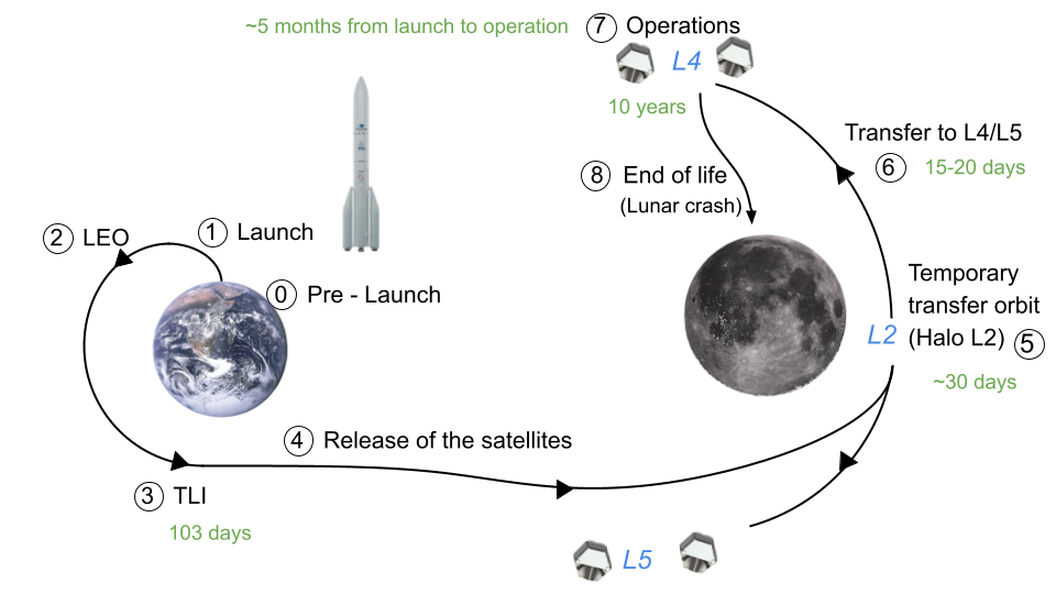
ConOps (Concept of Operation)
See figure below.
- Phases 0 & 1. Pre-launch and Launch: Satellites launched into Low Earth Orbit (LEO) aboard an Ariane 62.
- Phase 2. Commissioning: Calibration of instruments, Attitude and Orbit Control Systems (AOCS) alignment, and initial communication setup.
- Phases 3.& 4. Trans-Lunar Injection (TLI) by Ariane 62 upper stage and Release of the satellites.
- Phases 5. & 6. Transfer Phase: Maneuver to cislunar space via a temporary L2 Halo orbit, then to L4 and L5 using low-delta-v trajectories. (See trajectory analysis section for more details).
- Phase 7. Operational Phase: Continuous scanning of the Earth-Moon corridor using a tiled observation strategy; Regular data downlink and health checks; Shared observations between spacecraft for enhanced precision (see Scheduling below).
- Phase 8. End-of-Life: Controlled disposal of spacecraft (lunar crash) to ensure in-space sustainability (see sustainability section).
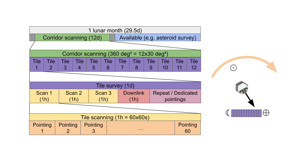
Scheduling
In the operational phase, the schedule of all 4 satellites is rythmed by the duration of a lunar month (29.5 days). During this period, half of the time is spent scanning the Earth-Moon corridor (60 deg large, 6 deg wide), with each section of the corridor scanned at least three times at a 1h frequency, to allow for initial orbit determination. Scanning the corridor in this linear fashion allows us to observe the regions with the optimal solar phase angle, maximizing the illumination and therefore the brightness of the objects observed. The schedule allows for more scans of each region of the corridor, or dedicated observations when an object is detected to better measure its orbit and characteristics if needed. When the Sun is on the opposite side of the corridor as the Lagrange point, the two satellites at that Lagrange point face away from the corridor to avoid being blinded by the Sun. During that time, they are available for secondary missions such as asteroid surveillance.
The following figure shows the scheduling in the operation phase, based on the lunar month duration.
¶ Results
¶ Trajectory Analysis
Usually takes care of (from ESA CEC 2022, "Mission Overview and Requirements"):
- Define the orbit and transfers of the spacecraft
- Define delta v over lifetime
- Calculate ground station contact time
- Calculate eclipse duration
- (End of life)
Requirements:
- REQ_TRAJ_01: Shall design trajectories to position 2 satellites at earth-moon’s L4 lagrange point and 2 satellites at earth-moon’s L5 Lagrange point.
- REQ_TRAJ_02: Shall design trajectories to make REQ_TRAJ_01 feasible in a single launch.
- REQ_TRAJ_03: Trajectory time shall be reasonably small compared to the 10 years mission duration.
- REQ_TRAJ_04: Trajectory maneuvers shall minimize the total delta-v of the mission
Before talking about the different methods to achieve the requirements, I would like to give some background concerning Lagrange points. Lagrange points arise as equilibrium points in the earth-moon-satellite system where the mass of the satellite is considered as negligible compared to those of the two primaries. This kind of system is frequently called the restricted 3 body problem (R3BP). In theory, a satellite positioned at those points would stay there forever but in reality, objects aren’t exactly located at the precise lagrange points but appear to orbit around those points when viewed from a synodic frame of reference (a.k.a. a frame of reference where the two primary bodies appear stationary).
An example of a family of orbits around L4 is depicted in Fig. Traj. 2. These particular orbits are in the same plane as the lunar orbit plane but other kinds of orbits also exist in three dimensions. The key point here is to understand that “orbits” around lagrange points become apparent when viewed under the synodic frame of reference.
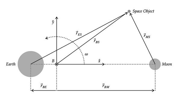
Fig. Traj. 1 - Satellite in the Earth-Moon synodic reference frame In this frame of reference only the satellite moves
[Tradeoffs]
Missing from report
[Justifications]
Missing from report
[Results]
Missing from report
¶ Configuration
Usually takes care of (from ESA CEC 2022, "Mission Overview and Requirements"):
- Create the configuration of the spacecraft
- Define the location of the equipment in the satellite
- Determine the MoI and CoG
Requirements:
- REQ-CON-001: Shall fit every subsystem inside the satellite respecting their individual requirements;
- REQ-CON-002: Shall fit four satellites inside the fairing of the the launcher;
- REQ-CON-003: Shall keep the center of mass of the satellite aligned with the thrusters to 5 cm along X and Y;
- REQ-CON-004: Should minimize the number of mechanisms.
[Design]
The configuration of the ASTRA spacecrafts is based on the ESA satellite CHEOPS. This small satellite of 1.5x1.5x1.5 m hosts a telescope with similar characteristics as the one required for ASTRA (see Payload). The main advantage of this architecture is that it uses fixed solar arrays and fixed antennas, reducing the number of mechanisms and therefore the number of possible failure points and complex parts.
Having fixed solar arrays is also justified by the fact that the telescope will have to always face away from the Sun ( 90 deg) to avoid being blinded by it. It is therefore meaningful to install the solar arrays on the opposite side of the telescope. Moreover, the use of a hexagonal-shaped structure enables to cover three faces with solar arrays, increasing the pointing range of the telescope while keeping a minimal power production (detailed in Power).
It has been decided to use fixed antennas for communication. This impacts the operation as it requires to halt the observations to point the antennas towards Earth to downlink data. This is completely compatible with the operation schedule, which provides enough time for communication. Because the satellites will be positioned at L4 and L5, the Earth is fixed from each satellite point of view. However, the Sun rotates around it in one lunar month. To be able to communicate with the Earth and still have the solar arrays illuminated, no matter the position of the Sun, two sets of antennas are used: one the +X face and one on the -Y face. They are moreover angled relative to these faces so that the telescope will not see the Earth (risk of blinding) when the antennas are facing the Earth.
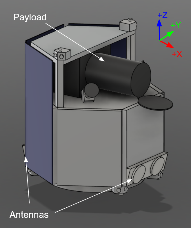
[Results]
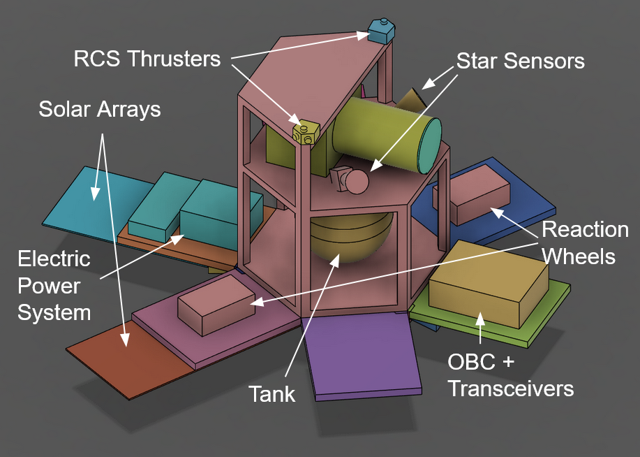
The figure below shows a simple CAD model of the ASTRA spacecraft. The telescope is shown with its shutter opened. It is placed on top of the satellite platform. On the three opposite faces are the solar arrays. The two sets of antennas are placed on the bottom of the +X and -X faces. The thrusters are positioned on the -Z face, with the launcher adapter.
The following figure shows the inside of the spacecraft by opening the different faces of the platform. The bi-propellant tank is positioned at the center and serves as a structural support. Each face can hold a volume of 500x700x240mm, where each subsystem’s components are positioned. Their placement is made to minimize harness (for example the batteries close to the solar arrays), to fulfill their requirements (two sets of reaction wheels on different faces to allow for attitude control) and to balance the satellite (according to REQ-CON-003). With the final configuration, the center of mass is located at (-0.049m, 0.004m, 0.65m) with the origin being at the center of the launch adapter (on the -Z face of the satellite). The satellite’s moments of inertia around the center of mass, and along the three axes, are (29.5kg.m, 13.2kg.m, 36.3kg.m). These values are used for dimensioning the AOCS.
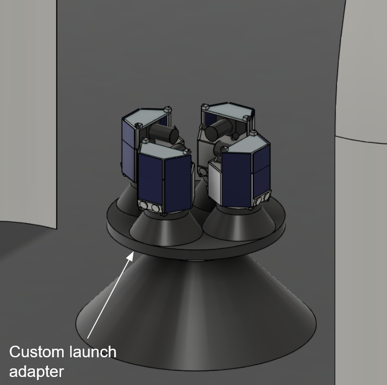
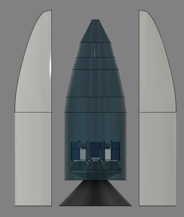
The two figures below show how the four spacecrafts fit inside the fairing of the Ariane 62 launcher. The spacecrafts are placed side-by-side on a custom launch adapter. This solution was preferred to stacking them to avoid having to oversize the structure of the satellites to hold the weight of up to three other satellites during launch (around the equivalent of 5t given the maximum acceleration of the launcher). The satellites are released sequentially to avoid collisions.
¶ Payload
Requirements:
- REQ-PL-001: Shall be able to detect moving objects up to an apparent magnitude of 21 (see Priedhorsky+2024 and Frueh+2021 )
- REQ-PL-002: Shall have a resolution smaller than 3 arcsec;
- REQ-PL-003: Shall weigh less than 100 kg;
- REQ-PL-004: Shall have a volume of less than 750x1400x500 mm;
- REQ-PL-005: Shall generate less than 400 Mbps of data, taking into account the operation schedule;
- REQ-PL-006: Shall have a field of view of at least 0.5 deg.
[Design]
The payload for the ASTRA mission is an optical telescope observing in the visible spectrum. It is largely inspired from the payload of the ESA CHEOPS satellite. Some modifications were made to have a larger field of view, while ensuring a minimal resolution (according to REQ-PL-002 and REQ-PL-006).
The MIS-003 requirement requires that the satellite shall observe the full Earth-Moon corridor. It is defined as a 60 deg large and 6 deg wide arc. Given the 0.75 arcsec resolution chosen, this gives 8300 Gpx for the full image of the corridor, at a depth larger than 21 mag.
To fulfill these needs, while not generating an amount of data impossible to transmit (according to REQ-PL-005), the payload has been sized according to the table below.
| Parameter | Value |
|---|---|
| Focal length | 1000 mm |
| Diameter | 350 mm |
| Field of view | 0.77 deg |
| Sensor size | 20x20 mm |
| Resolution | 0.75 arcsec |
| Image size | 4096x4096 px |
| Quantization | 16 bits/px |
The performance of this telescope would enable it to perform some really interesting astronomy studies (e.g. asteroid survey/follow-up observations) during the two weeks per month during which the satellites can’t observe the corridor.
¶ Structures & Mechanisms
Requirements:
- REQ-STR-001: shall ensure mechanical integrity during all mission phases ;
- REQ-STR-002: shall support the payload and the different subsystems ;
- REQ-STR-003: and have adapted dimensions for the fairing ;
- REQ-STR-004:shall shall survive static and dynamic loads during launch, including axial loads up to 6 g, lateral loads up to 2 g, shock loads from separation _ g ;
- REQ-STR-005: Shall respect minimum eigenfrequency requirements in beams : ≥ 20 Hz in longitudinal axis and ≥ 6 Hz in lateral axis ;
- REQ-STR-006: Shall not access a total mass of 15% of the satellite dry mass i.e —- ;
- REQ-STR-007 : Material selection shall meet ECSS-Q-ST-70-02 outgassing standards: TML ≤ 1%, CVCM ≤ 0.1% ;
- REQ-MEC-001 : Fixation interface shall be compatible with the Ariane 62 payload adapter (PLA6) with a qualified separation system ;
- REQ-MEC-002 : shall use reliable systems within 0,999 at 95% confidence. ;
- REQ-MEC-003 : Payload ;
[Tradeoffs]
The main factors that affect the satellite in terms of structure is the reliability against external events as shocks and the use of a
This trade off can be assessed by comparing the specific stiffness (E/rho) and yield strength/density ratio of different materials.
For the structural parts, three classical space-craft materials are compared : Aluminium alloy (Al 7075-T6) , Titanium alloy (Ti-6Al-4V) and Steel alloy (highly alloyed Cr-Ni).
In terms of specific stiffness, they are all really similar (around 0,0224 GPa·m³/kg), but in terms of tensile strength, Titanium has a great advantage, as seen in the table below.
| Material | Yield Strength (MPa) | Density (kg/m³) | Specific Yield Strength (MPa·m³/kg) |
|---|---|---|---|
| Aluminium alloy | 448 | 2800 | 0.160 |
| Titanium alloy | 830 | 4500 | 0.184 |
| Steel alloy | 900 | 7900 | 0.114 |
This means that Titanium alloy is ideal for critical load paths where weight and strength matter, where Al alloy offers a great trade-off with lightness and decently strong. Steel, while been really strong, is too heavy so used in high.load points if critical.
It is possible to create a Trade-off chart from a Trade-off table to clarify the best material for our use.
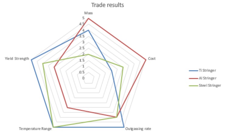
While Aluminium alloy has a better score with the addition of weight factors, the titanium alloy will also be selected in case of problematic loads.
For walls, honeycomb structure is chosen as it is the mainly used material for this application as in the Cheops mission. It will drastically reduce the weight and handle every subsystem as it is possible to fix with screws in it.
For the two platforms, carbon fiber composite (CFRP) is selected as it has the unique property to optimize the force distribution with the orientation of the different stacked layers of long fibers with only 5 to layers.
[Results]
According to the Ariane 6 User's Manual (Issue 2 Revision 0), the maximal compressive load in the Ariane 6.2 during the launch and release phase is 3.1 g (ESR Jettisoning) and the maximum of traction stress is around 6 g (at ESR End of Flight). From this, the loads on each critical part is derived :
The FAP (Flat adapter Port) experience 15,000 N in compression and 59,000 N in tension. These values are derived by applying the launch acceleration to the total mass of all four satellites mounted on the platform.
The SCA (Separation Clamp Adapter) endures up to 2,430 N in compression and 12,262 N in tension, based on the mass of a single satellite subjected to the same acceleration loads.
Each Stringer needs to support 1,962 N in compression and 817.5 N in tension, under the assumption of uniform distribution of the total payload mass and upper structure across six stringers.
The critical load ( Pcrit ) at which a slender, ideal column will buckle is given by:
Where:
- ( Pcrit ) = Critical buckling load (N)
- ( E ) = Young's modulus of the material (Pa)
- ( I ) = Moment of inertia of the cross-section (m⁴)
- ( L ) = Length of the stringer (m)
- ( K ) = Effective length factor = 0.5 for both ends pinned.
We have a maximum buckling of Pcrit = 2’004 N for Aluminium and Pcrit = 3’246 N for Titanium, considering 1 cm by 1.5 cm section and 80 cm length.
It is preferred to have a security factor of 1.5 to certify the integrity of the structure, the Titanium is chosen to stay at a pretty small section area, diminishing the mass.
Moreover, in terms of diminishing thermal expansion, critical to avoid movement of the Payload, a 80 cm stringer will expand by 13 mm for an Al alloy and 4 mm for a Ti alloy (DeltaT = 320°C)
To reduce bending moment, vibrations and compression of the x,y plane, the composite structure is chosen to be a [0,-45,45,90,45,-45,0] quasi-isotropic layup for an average height of 1mm. The honeycomb structure is an aluminium space-grade sandwich.
Finally the total mass calculated is 55.91 Kg with the sum of 6 honeycomb panels, 2 small stringers (80cm), 4 large stringers (150cm), 1 full composite plate and 1 half composite plate.
By adding the 25% of the structure mass for the bild, screws and fixations systems and another 10% of the mass for a safety factor, it appears the structure weighs 75.48 Kg.
In terms of mechanisms, the selected adapters are sourced directly from established manufacturers to ensure safety and reliability, as their components are backed by detailed datasheets and flight heritage, confirming their ability to withstand the calculated mechanical loads. The FAP is sourced from Moog with a tailored features of 4 clamp band fixation rather than 2 and the SCA are the (SAURON) 15” - from UAR X.
To ensure reliable operation during the opening phase of the shutter mission sequence, a brushless motor with a mass of 0.5 kg has been selected. The motor need to deliver a torque of 0.0013 N·m and achieves a rotation speed of 10°/s, values that are basics for brushless motors.
The shutter itself, made of aluminium and weighing 1.5 kg, is designed to be open smoothly after deployment, thereby minimizing the risk of contamination or damage at ground. It is also designed to close if necessary to avoid any cell damage by sun exposition or debris damage during orientation and displacement sequences.
¶ Propulsion
To design an efficient and reliable propulsion system for the satellite, a systems engineering approach was chosen. The following chapter begins by defining the requirements given by the customers for the propulsion system. Based on these requirements, a trade-off analysis is conducted using various evaluation criteria relevant to the mission. These criteria were developed in collaboration with other departments.
Following the trade-off analysis, the propulsion system is designed at the component level. This includes decisions on the propulsion type, propellant selection, and the sizing of thrusters, tanks, and piping. These design decisions are discussed in detail in the chapter Justifications. The report concludes with an overview of the mass and power budget, as well as an estimate of the total cost for the propulsion subsystem.
¶ [Requirements]
- REQ-PR-001:Smooth and safe Transfer: Enabling efficient and reliable transition from L2 to L4/L5 while considering the necessary deltaV.
- REQ-PR-002:Weight Optimization: Minimizing dry mass & necessary propellant.
- REQ-PR-003:End-of-Life Maneuver: Integrating deorbit capability for mission sustainability.
- REQ-PR-004:Satellite Dimensions: limited, Propellant tanks need to fit into the satellite.
- REQ-PR-005:Budget: Stay within the assigned budget.
¶ [Tradeoffs]
Considering all the requirements, we can now dive deeper into the system design and start with the decision for an electrical or chemical system. This choice significantly influences the overall development and sizing of both the propulsion system and the satellite itself.
To identify the most suitable system for the mission, discussions were held with the trajectory team, the systems engineers, the power subsystem, and the configuration department. The interfaces between propulsion and these subsystems made it necessary to involve all of the mentioned departments.
The selection process followed this structure:
Criteria Definition and Weighting:
All relevant criteria for the propulsion system were first identified and assigned a weighting based on their importance for the mission. The weighting scheme is the following: Reliability > Mass > Electrical Power Consumption = Thrust > Cost
System Evaluation:
Next, the main propulsion options, monopropellant, bipropellant, and electric propulsion, were assessed against each criterion. Points were awarded based on how well each option satisfied the weighted requirements. This can be seen in the following figure.
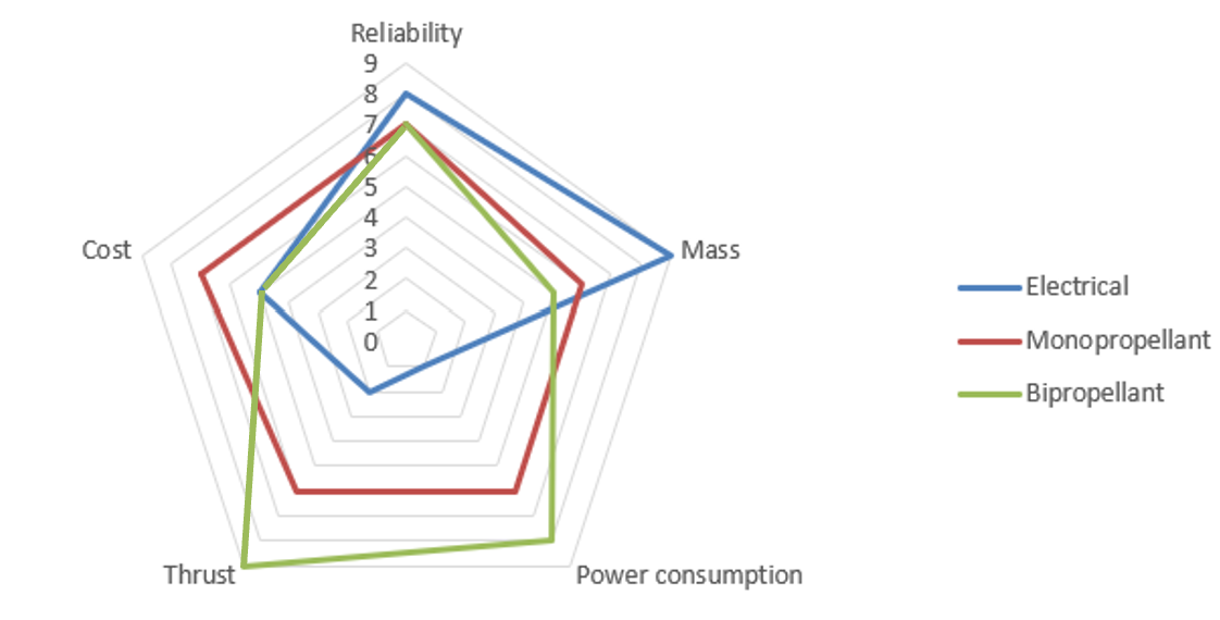
Final Decision:
Based on the final scores and the applied weightings, a decision was made. The selected solution is a bipropellant system using monomethylhydrazine (MMH) as fuel and dinitrogen tetroxide (NTO) as oxidizer.
Total Score Electrical Propulsion: 6
Total Score Monopropellant: 6
Total Score Bipropellant: 7
¶ [Justifications]
With the final propulsion type selected, the system development can now proceed at the component level. This chapter focuses on the detailed design of the individual subsystems that make up the propulsion system.
Propellant Mass
One of the most critical parameters for the overall satellite system is the required propellant mass. It was determined through several iterative loops, with increasing accuracy in each step.
The final deltaV requirement for the mission was given by the Trajectory and Sustainability departments. The total deltaV needed for the mission is 511 m/s.
Given this requirement, along with:
a specific impulse of Isp = 320 s (given by the propellant MMH/NTO),
the gravitational constant g0,
and the current total mass of the satellite,
the dry mass of the satellite, and thus the required propellant mass, can be calculated using the Tsiolkovsky rocket equation:
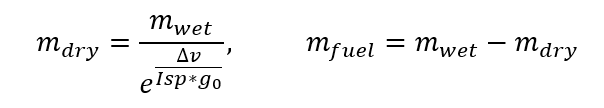
From the calculations above, the required propellant mass was determined to be m_fuel=65.49 kg. However, to ensure adequate system reliability and redundancy, a margin of 10% was applied. This results in a total propellant requirement of 72.05 kg.
The deltaV distribution across the individual maneuvers, along with the corresponding propellant consumption for each, is summarized in the following table:
| Maneuver | Needed DeltaV [m/s] | Needed Propellant [kg] |
|---|---|---|
| L2_dep | 50 | 6.89 |
| L4/L5_injection | 100 | 13.45 |
| Station keeping (10 years) | 300 | 37.88 |
| EOL Maneuver | 61 | 7.27 |
| Total | 511 | 65.49 |
Table with needed deltaVs]
Propellant Tanks
Once the required propellant mass was calculated, the sizing of the propellant tanks could begin. Due to the limited available space within the satellite, titanium tanks were selected. Titanium offers an excellent balance of low weight and high structural strength, making it well-suited for this application. Given the mixture ratio of 1:1.65 (MMH:NTO), the individual masses of fuel and oxidizer were calculated. Based on these values, we could get the total tank volume. Finally, the tank’s structural mass was calculated.
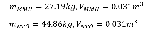
With a wall thickness of 1.5mm the total weight of the empty tank is m_Tank=6.04kg.
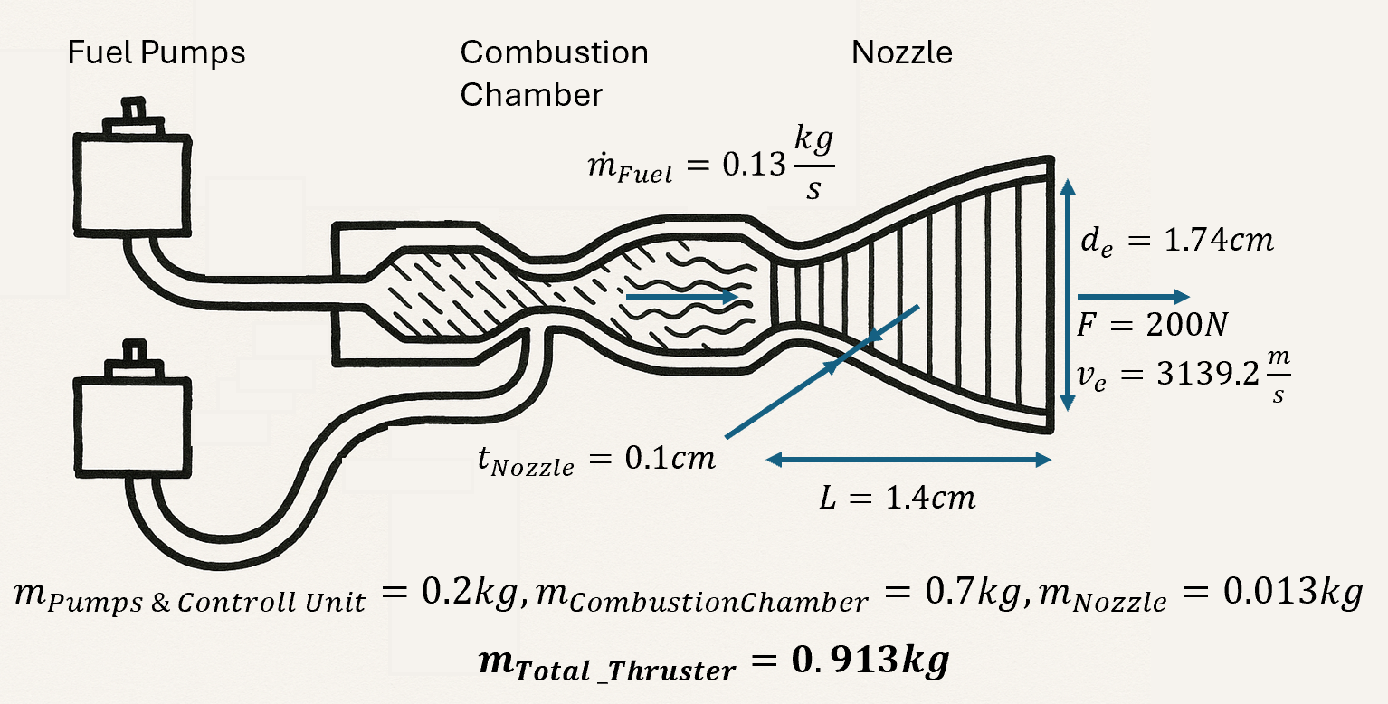
Thruster
To maneuver the satellite, a dual-thruster system is used, consisting of two Inconel nozzles, each providing 200N of thrust. This setup ensures increased reliability through system redundancy. Both thrusters are mounted on the underside of the satellite.
Due to the compact size of the nozzles, as seen below, the satellite can continue maneuvering if one thruster fails, since both are aligned to act through the center of mass.
The following parameters were calculated:
Propellant Pipes
To transport the propellant from the tank to the engine, propellant pipes are needed. The selected material for the pipes is titanium. This enables the pipes to be lightweight while also ensuring safe transport of the propellant to the engines. Based on the engine’s mass flow rate and the pipe diameter and length, a total mass of 0.04 kg was calculated.
¶ [Results]
The final propulsion system is based on a bipropellant configuration using MMH/NTO. The goal was to design a reliable propulsion system that operates effectively throughout the satellite's entire lifecycle. The resulting configuration delivers sufficient thrust while meeting all customer-defined requirements. The key system parameters for the propulsion subsystem are as follows:
Thruster: 2x 200N inconel thruster
Propellant: MMH/NTO
Tanks: Spherical titanium tanks
Total Power Consumption: 240W (40W Controls, 80W Pumps, 120W Heating)
Total Mass Propulsion System: 79,65kg (7,6kg dry mass / 72,05kg propellant mass)
Total Cost Propulsion System: 425.568 EUR
¶ AOCS
Requirements:
- REQ-AOCS-001: Shall fit every part of my subsystem within the available dimensions provided by configuration subsystem;
- REQ-AOCS-002: Shall design an AOCS with minimal power consumption (Bottom-Up);
- REQ-AOCS-003: Shall design an AOCS with total mass with respect to available mass given by System engineers;
- REQ-AOCS-004: Shall make a selection of reliable sensors/actuators to last around 10 years and be able to rotate our spacecraft in every direction.
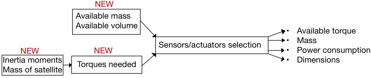
[Tradeoffs]
FACTOR 1 : ACTUATORS/SENSORS selection (theory)
The first step was to make a selection of sensors and actuators which would allow us to control the full attitude of our satellites. This part will detail everything for one single satellite. Here is the final choice :
SENSORS
Sun sensor: One on each of the eight external faces of the satellite
Gyroscope: One unit, inside the satellite, placed on one of the six ‘petals’
Star tracker: Two units, theoretically only one is necessary => redundancy
ACTUATORS
Reaction Wheels: Three units, one on each axis + one for redundancy
Gas thruster: Six units, to desaturate reaction wheels
Once it was done, I could start to search for existing datasheets in order to have first values to set in COMET for a first iteration.
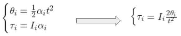
FACTOR 2 : TORQUES : Available vs Required
Then I started to derive both the required torques and available torques on each axis with the previous selection of actuators. Results were good. The required torques to operate a rotation of and angle theta [rad] around each axis were calculated with the following math :
FACTOR 3: Mass&Dimensions available
From this point, we did a second iteration on COMET and I considered my first constraints coming from other subsystems.
FACTOR 4: POWER CONSUMPTION
I did get a proper ‘available power’ value from the power subsystem but I kept trying to minimize it as much as possible.
As the iterations kept going, I had to change my selection, doing a tradeoff between mass & dimensions and torques needed, always taking long reliability as first priority and minimizing power consumption.
Torques needed, and mass available kept changing over the weeks due to variations of the total mass and moment of inertia.
[Justifications]
As mentioned above, the actuators-sensors package was constantly changing. I wanted to add as much redundancy as possible but I was limited by my available mass and the power consumption. Some additional elements have also been considered like an Earth sensor but later cancelled because of its inefficiency that far from Earth. A controlled moment gyroscope was also part of the first selection but was the most heavy (~15kg) and the most power consuming (~25W) element above all. I noticed during my calculations of torques that other actuators were sufficient.
We chose to put a sun sensor on each face of the satellite as an insurance, it would maybe not be necessary to have that much but these devices are light and low consuming.
While reaction wheels and gyroscope are located inside the satellite, on one of the six ‘petals’ (see Configuration subsystem). Most of the sensors and actuators are located on the external faces of the satellite. Locations and thrust directions of gas thrusters have been determined to allow the three rotations (around x,y and z axis) while not interfering with telescope and star tracker FOV.
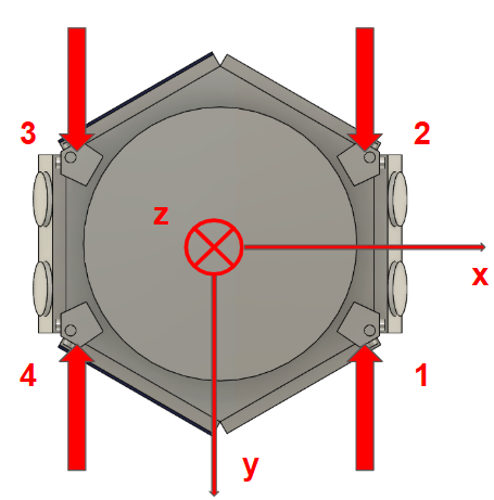
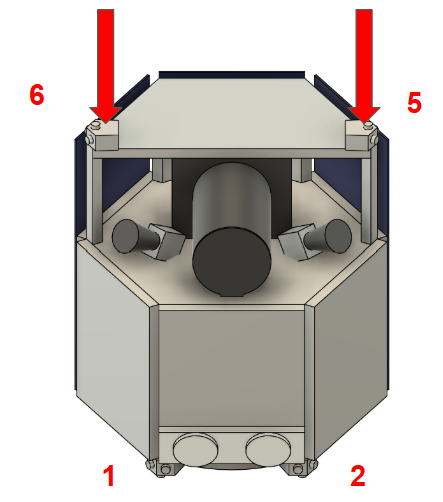
GasThrustersLocation]
[Results]
¶ Sensors & Actuators - Mass and Power Budget
| Component | Quantity | Mass [kg] (per unit / total) | Mean Power [W] (per unit / total) | Peak Power [W] (per unit / total) |
|---|---|---|---|---|
| SENSORS | ||||
| Sun Sensor | 8 | 0.65 (5.2) | 0.3 (2.4) | 0.4 (3.2) |
| Gyroscope | 1 | 4.6 (4.6) | 25 (25) | 32 (32) |
| Star Tracker | 2 | 2 (4) | 10 (20) | 12 (24) |
| Sensors Subtotal | 13.8 kg | 47.4 W | 59.2 W | |
| ACTUATORS | ||||
| Reaction Wheels | 4 | 5 (20) | 5 (20) | 8 (32) |
| Gas Thrusters | 6 | 0.6 (3.6) | 5 (30) | 5 (30) |
| Actuators Subtotal | 23.6 kg | 50 W | 62 W | |
| TOTAL | 37.4 kg | 97.4 W | 121.2 W |
¶ Torques available
This resumes all the torques available for rotations around the x,y and z axis passing through the center of mass. One main assumption has been made : the center of mass is on the z axis shown above.
| Component | Torque [Nm] x axis | Torque [Nm] y axis | Torque [Nm] z axis |
|---|---|---|---|
| Thruster 1 | 0.065 | 0.135 | 0.15 |
| Thruster 2 | 0.065 | 0.135 | 0.15 |
| Thruster 3 | 0.065 | 0.135 | 0.15 |
| Thruster 4 | 0.065 | 0.135 | 0.15 |
| Thruster 5 | 0.15 | 0 | 0.15 |
| Thruster 6 | 0.15 | 0 | 0.15 |
| Reaction Wheels | 0.2 | 0.2 | 0.2 |
| Total torque available | 0.76 | 0.74 | 1.1 |
¶ Torques required
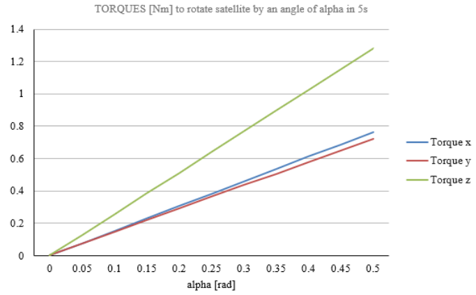
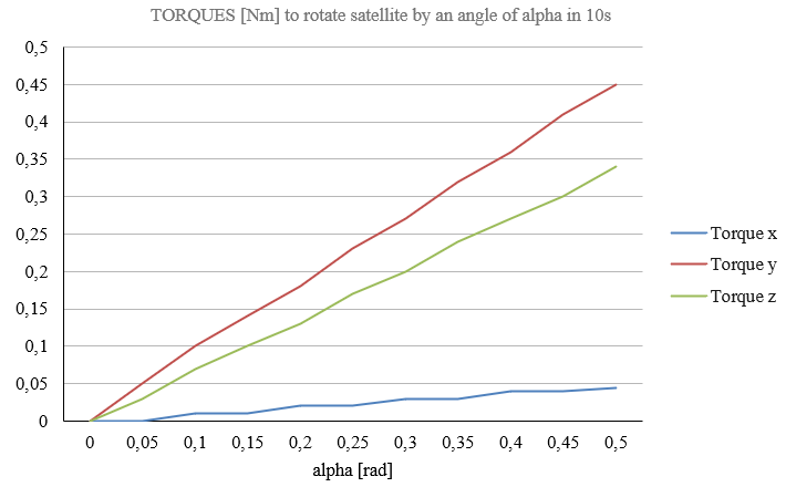
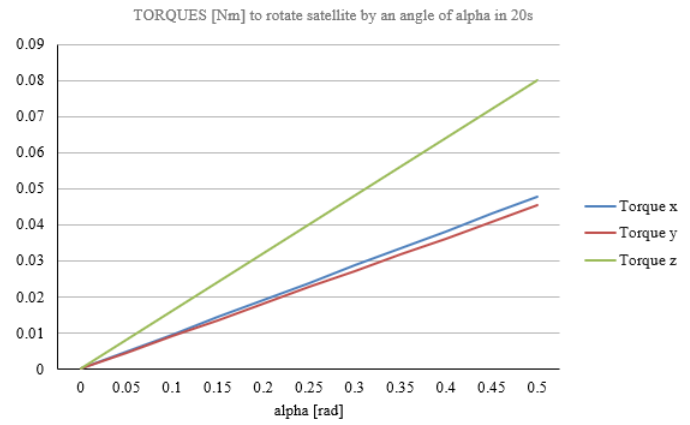
To face available torques, I computed required torques to rotate the satellite by an angle of alpha [rad] at different fixed times. Here are the plots:
Since we don’t have explicit requirements about it in the documentation we had, we can only try to derive a torque from the technical notes:
¶ Observation Parameters
- Pointing scheme: 3 sets of 60 pointings (total 180 pointings/day)
- Integration time per pointing: 60s
- Total available time: 24 hours (86,400s)
¶ Time Budget Calculation
180 × (60s integration + slew time) ≤ 86,400s
→ Maximum slew time per pointing ≈ 20s
¶ Slew Geometry
- Field of View (FOV): 0.77 deg²
- Assumed square FOV side length: √0.77 ≈ 0.88°
- Required slew distance between pointings: 0.88° ≈ 0.018 rad
¶ Link with our plots
On our 3 plots we can determine what torque would be necessary to do such a rotation around each axis from different slew times:
| Temps \ Axe | Torque X (Nm) | Torque Y (Nm) | Torque Z (Nm) |
|---|---|---|---|
| 5s | 0.32 | 0.30 | 0.50 |
| 10s | 0.05 | 0.17 | 0.13 |
| 20s | 0.019 | 0.018 | 0.032 |
All these values of torques are available with our design.
If I were to continue the project, I would focus on finding more efficient ways to control the rotations by studying the thrust curve documentation. So far, I’ve simply assumed it was feasible, given that our gas thrusters can produce thrust in multiple directions to counter each rotation.
¶ CDHS
¶ Applicable Documents
- CDH_REF_01 - ECSS
- CDH_REF_02 - ESA Computation sheet
- CDH_REF_03 - SMAD
¶ Mission Statement
The Command and Data Handling System shall provide the satellites with the necessary infrastructure to process, store and exchange information — such as commands and data — with the ground segment.
This mission statement was further refined as the sources of information were readily identified in the form of the satellite itself — hereinafter referred to as the Telemetry, Tracking and Command (TT&C) — and the payload. The C&DH system therefore needed to be designed so as to accommodate both pipelines simultaneously.
¶ Design Methodology and Justifications
¶ Overarching Constraints
Standards and regulations applying to the present scenario were taken into account in the design of the C&DH System. Most importantly for this project, standardized margins of safety are provided in [CDH_REF_01]. Furthermore, the available ground infrastructures were assumed to be limited to the ESTEC’s network of ground emitters and receivers, a list of which is provided in [CDH_REF_02]. Knowledge of the ground segment was taken into account and included into the system’s link budget.
For the purpose of this project, the design was simplified by strictly limiting the selection of components to pre-existing commercial off-the-shelf (COTS) options.
Finally, other subsystems, particularly the Power Subsystem and Configuration Subsystem, will impose lower-level design constraints, which were taken into account within the technical specifications of the subsystem.
¶ Figures of Merit
Figures of Merit (FoM) were used to facilitate trade-offs by providing objective and quantifiable elements of comparison between various design options. Moreover, by defining a set of FoMs, one obtains the core components used in high-level requirements elicitation.
| ID | Name | Type | Metric | Range |
|---|---|---|---|---|
| CDH_FOM_01 | Mean Time between Full Transmission | Minimization | Duration [h] | [0;+∞[ |
| CDH_FOM_02 | Mean Spatial Resolution Loss | Minimization | 1 - \frac{\text{Data Size Transmitted}}{\text{Data Size from Payload}} | [0;1] |
| CDH_FOM_03 | Mean Path Redundancy | Maximization | number of path available to transmit data from source to destination | [1;+∞[ |
| CDH_FOM_04 | Modularity | Maximization | [1;+∞[ |
¶ Model-Based Approach
The design process was centered around the establishment of a link budget. Beyond providing direct insight into the feasibility of each option, it also provides a quick and efficient way to extract the values of the aforementioned FoMs. The equations driving the models can be found in [CDH_REF_03].
¶ C&DH System Architecture and Constraints
The first step in designing the Command and Data Handling (C&DH) system was selecting an overarching architecture—determining how to structure the various functionalities into distinct components. Guided by the chosen set of Figures of Merit (FoMs), a bus-modular architecture centered around a centralized on-board computer (OBC) was adopted. This approach offered a balanced trade-off between performance and modularity, with the added benefit of simplified reliability mechanisms through the integration of multiple redundant units onto the bus.
However, a key limitation of this architecture is the single point of failure (SPoF) introduced by the central bus, specifically the OBC. To address this vulnerability, enhanced redundancy mechanisms were incorporated into the bus design.
¶ RF Pipelines High-level Design and Constraints
The S-Band and X-Band were selected for the TT&C and Payload Downlink, respectively. These frequency bands are commonly employed in space missions and are well-suited to ESTEC’s ground infrastructure. It is also important to note that, while the Payload Downlink operates over a single RF channel, the TT&C subsystem requires full duplex communications to accommodate both uplink and downlink operations.
¶ Requirements
Together, the previously discussed constraints, selected Figures of Merit, and the high-level architectural and design decisions formed a comprehensive foundation for the system’s technical specifications. As a result, the subsequent lower-level design was reduced to finding the best-fitting combination of COTS components.
- REQ_CDH_01: The command and data handling role shall cover the design and configuration of the command and data handling subsystem.
- REQ_CDH_02: The C&DH subsystem shall support duplex TT&C communications.
- REQ_CDH_03: The C&DH subsystem shall support the payload’s downlink channel.
- REQ_CDH_04: The C&DH subsystem shall ensure the payload’s data be downlinked in at most [1] h.
- REQ_CDH_04: The C&DH subsystem shall ensure the payload channel’s mean spatial resolution loss be at most [0.01].
- REQ_CDH_05: The C&DH subsystem shall ensure the mean path redundancy be at least [3]
- REQ_CDH_06: *The C&DH subsystem’s design components shall withstand all environmental conditions encountered for the full mission duration.
- REQ_CDH_07: *The C&DH subsystem shall ensure that all channels be compliant with [CDH_REF_01].
- REQ_CDH_08: *The C&DH subsystem’s total mass shall be at most [23 kg].
- REQ_CDH_09: *The C&DH subsystem’s peak power draw shall be at most [68.8 W].
Mean Spatial Resolution Loss
¶ Results
The final CD&H System design directly follows from the above system architecture, for a total mass of 22.73 kg. The system’s components are listed in the following tables:
¶ Antennas
| Name | Quantity | Band | Mass | Peak Gain |
|---|---|---|---|---|
| Anywaves S-Band TTC Antenna | 2 | S-Band | 0.59 kg | 6.5 dBm |
| Anywaves High Gain X-Band Downlink Antenna | 2 | X-Band | 0.98 kg | 15.5 dBm |
¶ Transceivers
| Name | Quantity | Band | Mass | Power Draw | Tx Power | Data Rate |
|---|---|---|---|---|---|---|
| RocketLab Frontier-S | 1 | S-Band | 0.59 kg | 6.8 W | 28.5 dBm | 20 Mb/s |
| LL3Harris CXS-1000 | 2 | X-Band | 5 kg | 12 W | 40 dBm | 400 Mb/s |
The chosen configuration — two X-Band transceivers and one S-Band transceiver — is a direct consequence of the capabilities of both transceivers. Firstly, the Frontier-S have two redundant channels per direction (i.e. two Tx and two Rx channels). Secondly, should the Frontier-S fail, the capabilities of the CXS-1000 would allow for the entire TT&C traffic to be passed through the X-Band channels without much impact on the Payload Downlink operations.
¶ On-Board Computer
| Name | Quantity | Mass | Power Draw | Storage Capacity |
|---|---|---|---|---|
| Beyond Gravity Next-Gen OBC | 1 | 9 kg | 38 W | 789 Gb |
Beyond Gravity’s Next-Gen OBC was chosen as it not only has sufficient storage capacity to support the Paylaod’s operations but also incorporates two redundant units — as if there were two identical OBC.
¶ Operational Modes
The modes of operations are not within the scope of the C&DH subsystem. The system’s design and configuration instead ensures that any potential operational needs could be fulfilled. The power needs for said operations were handled by the Configuration and Power subsystems.
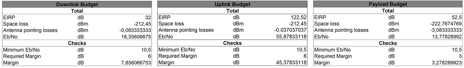
¶ Link Budgets
The link budgets for each RF channel were constructed around the SNR per bit (), which are then compared against the margins specified in the requirements. Each budget takes the emitter, the receiver and the ‘path’ — the distance traveled in free space. As the chosen frequency bands were of small-enough frequency, the effects of the atmosphere, especially rain fade, could be neglected.
¶ Appendix
¶ Link Budget Main Equations
These are the simplified calculations used to compute the budgets for each RF channel. Note that the antenna pointing losses are negligible and thusly omitted from this index. The minimum , against which the margin is computed, is set to 10.5 dB as per [CDH_REF_02]
Effective radiated power: Total power emitted at the transmitting antenna
| Symbol | Name | Units |
|---|---|---|
| P_ | Transmitter Power | dBm |
| G_ | Transmitter Antenna Gain | dBi |
| L_ | Tx-side Lines Losses | dB |
Free Space Losses: Lost power as the wave travels through free space
| Symbol | Name | Units |
|---|---|---|
| Distance travelled in Free Space | km | |
| Frequency | GHz |
SNR per bit: Normalized signal-to-noise ratio w.r.t to the frequency bandwidth
| Symbol | Name | Units |
|---|---|---|
| T_ | Rx-Side Noise Temperature | K |
| Data Rate | b/s |
¶ Power
¶ Introduction
The Electrical Power Subsystem (EPS) was tasked with providing reliable and autonomous power generation, storage, and distribution over a mission duration of ten years. The system was constrained to operate solely on solar energy and required to support critical mission modes including continuous observation and multiple daily communication sessions.
The design philosophy adopted for the EPS prioritized mechanical simplicity and robustness. As such, the solar arrays were dimensioned first, based on fixed-side panel mounting, and the energy storage system was then sized to compensate for illumination variability. This approach allowed early integration with configuration and thermal teams, and simplified the interface with AOCS by avoiding deployable or steerable panels.
A late-stage update from the CDHS team led to a significant design shift: instead of assuming one communication session per day, the satellite was expected to perform up to six. Given available mass margins, the battery system was scaled accordingly through modular replication rather than reworking the entire energy model, ensuring feasibility within the project timeline.
¶ Requirements
The EPS was structured into three core functions:
- Generation, via solar arrays,
- Storage, via rechargeable battery packs,
- Distribution, via a fixed harness delivering conditioned power to all satellite subsystems.
Functional Requirements:
- Shall supply electrical power to all subsystems throughout all mission phases.
- Shall ensure continuous operation during sunlight and eclipse-like events (e.g. Earth shadow during communication).
- Shall integrate with the satellite's overall configuration and thermal environment.
Performance Requirements:
- Shall operate for a minimum of 10 years in orbit.
- Shall rely exclusively on solar energy (radioisotope sources prohibited).
- Shall include redundant battery capacity to tolerate cell-level failures.
- Shall keep total EPS mass in line with mass budget allocation.
Assumptions:
- The mission profile does not include true orbital eclipses (no passages behind Earth or Moon).
- The satellite is assumed to maintain at least partial solar orientation in all operational phases, enabling continuous or near-continuous power generation.
- Communication sessions are considered power-intensive and can coincide with suboptimal solar incidence; battery storage is dimensioned to handle these conditions.
¶ Power Generation – Solar Arrays
Design Approach and Assumptions
The sizing of the solar arrays was the starting point for the EPS design. The strategy adopted was to first fix the surface available for solar energy collection based on the spacecraft’s external geometry and thermal constraints. Battery storage was then sized to compensate for energy shortfalls during periods of low illumination. This design sequence ensured early compatibility with the configuration and thermal teams and allowed the elimination of deployable or steerable panels.
Three lateral faces of the satellite were assigned to fixed solar panels. Each face provided approximately 0.8 m², for a total active area of 2.4 m². This layout allowed for at least one panel to maintain a favorable orientation to the Sun throughout most operational phases.
According to the trajectory and operations teams, observation phases occur under near-optimal Sun incidence, enabling maximum power generation. Communication windows, on the other hand, coincide with constrained spacecraft orientations and result in the worst illumination angles (27°, with respect to the most illuminated side panel), representing the power minimum.
Given the stable orbital configuration and the mission’s predictable scheduling (see Operations), a more detailed, time-resolved power mode analysis was not deemed necessary. The power subsystem was therefore dimensioned based on two bounding cases—DAY and ECL—which represent the best and worst illumination scenarios respectively. This approximation was validated in coordination with the CDHS and AOCS teams and ensures robustness across all intermediate states.
Environmental and Cell Characteristics
| Parameter | Value | Units |
|---|---|---|
| Solar constant (lunar distance) | 1360 | W/m² |
| Worst-case sun angle (communication) | 27 | degrees |
| Mission duration | 10 | years |
| Solar cell technology | GaAs CTJ30 | – |
| Ideal efficiency (BOL) | 29.0 | % |
| Derating due to temp, transmission, angle | 64.8 | % |
| Yearly degradation | 3.0 | % |
| Cumulative degradation over mission | 0.737 | factor |
The effective BOL and EOL power densities were computed as:
Power Generation Performance
Power generation was evaluated in two distinct modes:
- DAY: observation phase with near-optimal solar incidence
- ECL: communication phase with worst-case incidence (27°)
| Scenario | Power BOL | Power EOL | Units |
|---|---|---|---|
| Observation (DAY) | 388.7 | 286.7 | W |
| Communication (ECL) | 88.2 | 65.1 | W |
Total power was computed from the surface area and power densities:
Mass Breakdown
| Component | Value | Units |
|---|---|---|
| Cell surface density | 0.9 | kg/m² |
| Structural layer + frame | 4.5 | kg/m² |
| Total panel surface (3 panels) | 2.535 | m² |
| Solar cell mass | 2.28 | kg |
| Support structure + integration mass | 11.4 | kg |
| Total solar array mass | 13.7 | kg |
Each panel contributes approximately 4.56 kg to the system. The integration mass estimate includes substrate, interconnects, and framing. Values were coordinated with the configuration and thermal teams to ensure mechanical compatibility.
Technology Selection
The CTJ30 solar cells selected for the mission are fully qualified according to ECSS-E-ST-20-08C and offer a BOL efficiency of 29.5% under AM0 conditions. Their high radiation resistance and stable output over time justified the assumption of a 3% annual degradation rate. Full specifications are provided by the manufacturer (CESI, 2020).
¶ Batteries
Power Budget and Energy Requirement
Battery sizing was driven by the need to cover power deficits during 1-hour communication sessions, which occur under worst-case illumination (ECL mode). The CDHS team confirmed late in the study that up to 6 such sessions per day were feasible. To preserve the integrity of the design timeline, the battery system was scaled by replication—one pack per session—without redesigning for this new regime.
Power demand per subsystem was estimated for both operational extremes:
| Subsystem | High Illumination | Low Illumination (ECL) |
|---|---|---|
| CDHS | 68.8 W | 68.8 W |
| AOCS | 97.4 W | 97.4 W |
| Payload | 60.0 W | 2.4 W |
| Other subsystems | 0.0 W | 0.0 W |
| Total | 226.2 W | 168.6 W |
The solar arrays generate only 65.1 W under ECL conditions at EOL, resulting in a net deficit:
This shortfall must be supplied by the battery over a 1-hour communication session.
Battery Sizing
Battery capacity was calculated using the standard formula from the course:
Where:
- Cr: required capacity [Wh]
- Pe = 103.5 , W: communication power deficit
- Te = 1 , h: communication window duration
- DOD = 0.5: Depth of Discharge
- = 1.0: assumed efficiency (conservative)
Plugging in:
Each pack must thus provide at least 207 Wh usable energy.
Pack Design and COTS Technology
The chosen technology is the EaglePicher LP33037 Li-ion NMC cell, with the following characteristics:
| Parameter | Value | Unit |
|---|---|---|
| Nominal voltage | 3.6 | V |
| Capacity per cell | 60 | Ah |
| Energy per cell | 216 | Wh |
| Mass per cell | 1.6 | kg |
| Specific energy (datasheet) | 160 | Wh/kg |
| Temperature range | -20 to 60 | °C |
Each battery pack contains 4 LP33037 cells in parallel:
This provides over 2× the required session energy, offering redundancy through overcapacity rather than duplication.
System Sizing and Architecture
| System Parameter | Value | Unit |
|---|---|---|
| Energy required per session | 103.5 | Wh |
| Usable capacity per pack | 432 | Wh |
| Packs used per day | 6 | – |
| Number of cells per pack | 4 | – |
| Mass per pack (est.) | ~6.8 | kg |
| Total battery mass | ~40.8 | kg |
The modular architecture simplifies power management, tolerates partial degradation, and ensures each session can be powered independently.
Technology Selection
The LP33037 cell was selected for its high energy density, space-qualified stainless-steel enclosure, and thermal robustness. Its cycle life and electrical characteristics exceed mission needs. Over-sizing via modular replication ensured rapid integration after late mission requirement updates.
¶ Harness
- Power distribution harness mass was estimated at 10% of total dry mass.
- Distribution assumed to be redundant with basic fault isolation.
- No custom topology optimization performed due to limited iteration time.
¶ Conclusion
Subsystem Totals
| Component | Mass (kg) | Notes |
|---|---|---|
| Solar arrays | 13.7 | Includes structural, support, and panel mass |
| Batteries | 40.8 | 6 packs, each composed of 4 LP33037 cells |
| Harness | 40.0 | Estimated as 10% of total satellite dry mass |
| Total EPS | 94.5 | Compliant with system mass budget |
Remarks
- The Electrical Power Subsystem meets all functional and performance requirements over the 10-year mission duration.
- Battery capacity was conservatively oversized by replicating a validated 1-session/day configuration across 6 sessions, avoiding last-minute redesign while maintaining margin.
- The EPS integrates seamlessly with AOCS (orientation constraints), CDHS (session frequency), thermal management, and structural layout.
- For limitations, deferred tasks, and improvement directions, refer to the Lessons Learned on Power.
¶ Thermal
Requirements:
- REQ_TH_1: Shall identify equipment with the most constrained operational and survivability temperature range.
- REQ_TH_2: Shall identify thermal phases during operations, with their transient and steady-state characteristics.
- REQ_TH_3: Shall identify the coating material that requires the minimal active thermal control.
- REQ_TH_4: Shall identify the active thermal equipment if needed.
- REQ_TH_5: Shall define and update sub-system power and mass budget.
[Tradeoffs]
- Use of passive versus active thermal control strategies.
- Dimensioning to keep all elements in their operational or survivable temperature range
- Use of protective thermal layer against thermal load generated by the main propulsion system during manoeuvering
[Justifications]
- The nominal operating temperature of the spacecraft is defined between -20°C to 40°C, as this is the batteries operational range. (REQ_TH_1)
- The solar panels have an operating temperature between -100°C and 125°C, an emittance coefficient of 0.82 and an absorptivity coefficient of 0.63. (REQ_TH_1)
- The eclipses are rare and short, they are thus assumed negligible which means the system stays at steady state. (REQ_TH_2)
- This far away from Earth, the albedo reflection and IR radiations are negligible, the only radiation into the system is direct Sun radiation, which is assumed constant at 1327 W/m^2, as 2*(Earth-Moon distance) <<< Earth-Sun distance. (REQ_TH_2)
- The spacecraft slowly oscillates between solar panels fully facing the sun and half-facing the sun, these are the two points where the steady-state temperature will be evaluated. (REQ_TH_2)
- The spacecraft is modelled as a two-body thermal system: the solar panels and main body are separated by a small gap, but interact through radiation. The faces exchanging radiation are parallel and close to each other, so the view factor is 1. (REQ_TH_2)
The next steps are is:
- Evaluate steady-state temperatures for a range of typical spacecraft coatings, for the two different orientations w.r.t. the Sun (REQ_TH_3)
- If there is a material that keeps the spacecraft within its operational temperature range in the two orientations, keep it (REQ_TH_3)
- If no material keeps the spacecraft within its operational temperature range in the two orientations, evaluate the use of heating and/or cooling systems (REQ_TH_3/REQ_TH_4)
- Once having determined an appropriate material and active thermal control systems, evaluate their combined mass (REQ_TH_5)
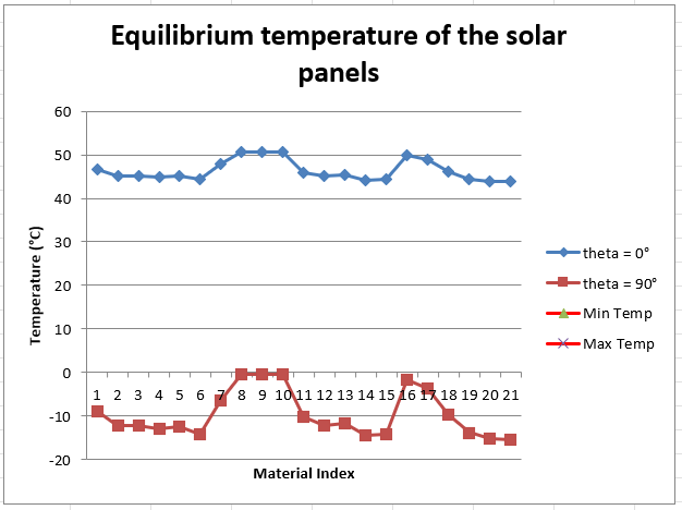
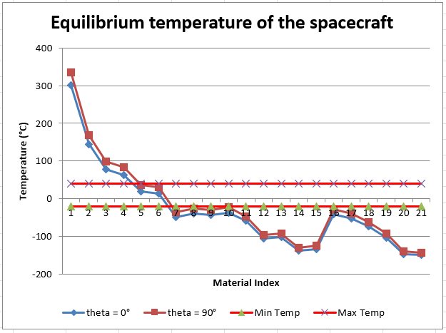
[Results]
- With two coating materials, Polished aluminium and Aluminized Kapton (with the aluminium outside), the spacecraft stays passively within its operational temperature range. Thus, the spacecraft does not require any active thermal control.
- With all coating materials for the spacecraft, the solar panels stay well within their operational temperature range.
- Choosing the lighter one of the two possible coating materials, Aluminized Kapton, with a thickness of 0.125mm, we get a coating mass of 1.23 kg.
- There was no time to evaluate the heating due to the engines’ operations, so a margin of 1 kg of the same material was added, to achieve the Thermal Subsystem’s final mass of 2.23 kg.
¶ Space Sustainability
Requirements:
- REQ_LCA_01: The sustainability role shall return a value for the materials impact of the entire system.
- REQ_LCA_02: The value that represents the materials impact of the entire system shall be between 0 and 1, where 0 represents the worst environmental impact and 1 is the best environmental impact.
- REQ_LCA_03: The sustainability role shall return a value that represents the materials impact of the structure subsystem.
- REQ_LCA_04: The value that represents the material impact of the structure subsystem shall be between 0 and 1, where 0 represents the worst environmental impact and 1 is the best environmental impact.
- REQ_LCA_05: The sustainability role shall return a value that represents the environmental impact of the power subsystem.
- REQ_LCA_06: The value that represents the materials impact of the power subsystem shall be between 0 and 1, where 0 represents the worst environmental impact and 1 is the best environmental impact.
- REQ_LCA_07: The sustainability role shall return a value that represents the materials impact of the propulsion subsystem.
- REQ_LCA_08: The value that represents the materials impact of the propulsion subsystem shall be between 0 and 1, where 0 represents the worst environmental impact and 1 is the best environmental impact.
- REQ_EXT_FORCES_01: The sustainability role shall return a value ranging between 0 and 1, where 1 represents a system that delivers similar value under normal or degraded conditions. 0 represents a failure of the system under degraded conditions.
- REQ_SCORE_01: The sustainability role shall return a value ranging between 0 and 1, where 1 represents the most sustainable system that can be designed at the current state-of-the-art and 0 is the least sustainable system that can still meet functional requirements.
- REQ_EOL_01: The sustainability role shall provide a Concept of Operations for the End-of-Life strategy.
- REQ_EOL_02: The sustainability role shall return a score between 0 and 1, where 1 represents the strategy with the highest merit in terms of DeltaV and debris risk, and 0 the lowest.
- REQ_TRADEOFF_ANALYSIS_01: The system shall provide a launcher for the mission, which is compliant with the needed mass.
- REQ_SAFETY_01: The sustainability role shall return ranging between 0 and 1, where 1 represents a totally safe system where all hazards are mitigated, and 0 represents a very unsafe system where the overall function is compromised.
[Tradeoffs]
There are 2 tradeoffs that are performed by the sustainability role. The other tasks purely serve a purpose of assessment. These two tradeoffs are the launcher selection and the end of life strategy. These are concurrently performed with the systems engineers. The objectives and alternatives for both are listed below:
Launcher Selection:
Objectives:
- Minimize Atmospheric impact
- Maximize Affordability
Alternatives: (European)
- Ariane 62
- Ariane 64
- Vega C
Decision support for the end-of-life strategy:
Objectives:
- Minimize risk of debris generation
- Minimize deltaV
Alternatives:
- Heliocentric orbit
- Stay in place
- Graveyard orbit
- Crash on the moon
[Justifications]
Launcher selection
From the information that we have, we establish an index for each of the propellants (See table 1). We are then able to tailor the assessment to any launch vehicle using its propellants composition and performing a weighted average (See equation 1). An implementation of the index can be observed on the figure 1 with the currently operational launchers and the future ones, where the index is re-normalized for the sake of the graph. We can clearly see that the selected launcher (Ariane 62) is currently the highest performing in terms of atmospheric impact.
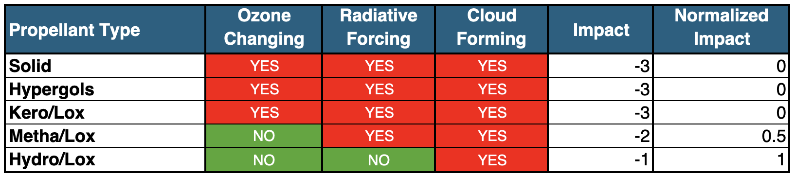
Table 1: Atmospheric Impact of Typical Launch Vehicle Propellants. Data on atmospheric effects from “Space sustainability isn’t just about space debris: On the atmospheric impact of space launches” (Sirieys et al., 2022).
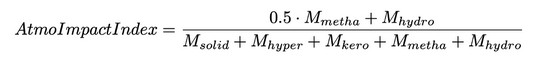
Equation 1: Index for the Evaluation of the Atmospheric Impact of a Launch Vehicle. Solely based on the Propellants of the Launch Vehicle.
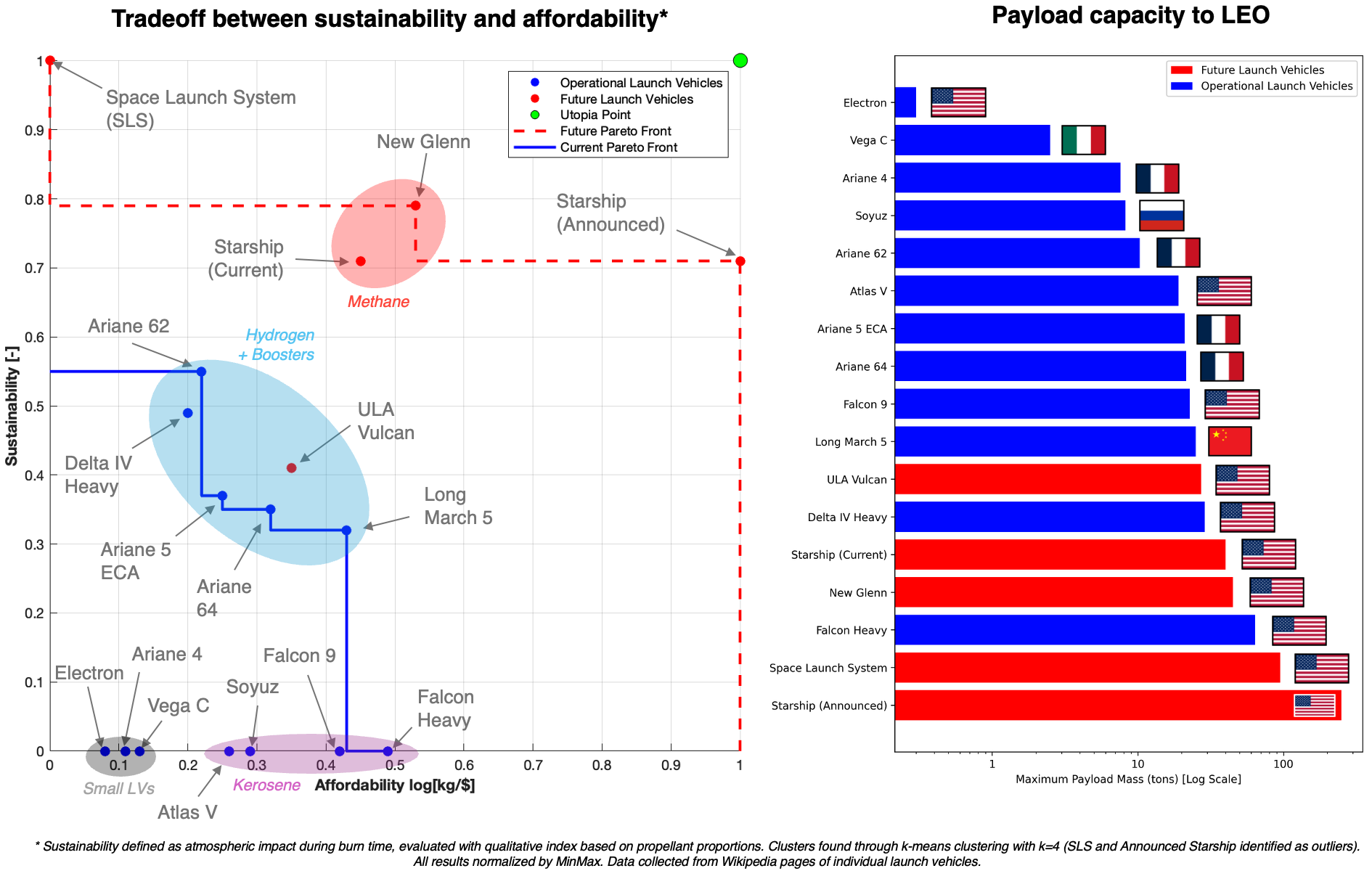
Figure 1: Decision Support for the Selection of Launch Vehicle. Based on a tradeoff between sustainability and affordability. Sustainability Index normalised from Equation 1. Non European Launch Vehicle Displayed as Indication but Out-of-Scope for the Mission Requirements. Clusters found through k-means clustering with k=4 (SLS identified as outlier). All results normalized by MinMax. Own Figure. Data on future launch vehicles is indicative and uncertain.
End-of-Life Strategy:
The figure 2 shows the selection of the end-of-life strategy among the different alternatives. Uncertainties are identified and mitigated through additional propellant, enabling the definition of Real-Options to increase the flexibility of the strategy (See CONOPS in the results section, Figure 5).
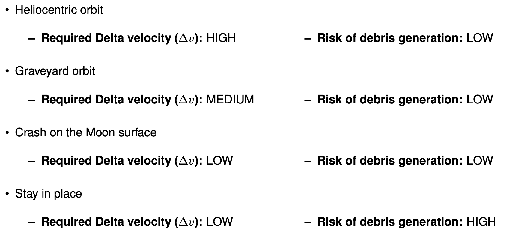
Figure 2: Tradeoff Analysis for the Selection of the End-of-Life Strategy. Own Figure.
Then to establish the score of the end-of-life strategy, we use the following qualitative rationale:
- 1: Under degraded conditions, the end-of-life strategy can be performed with a low delta-V, compliance with regulations is ensured, and the risk of debris generation can be considered low.
- 0.66: Under degraded conditions, the end-of-life strategy can be performed with a high delta-V or compliance with regulations is not ensured, or the risk of debris generation is high.
- 0.33: Under degraded conditions, the end-of-life strategy can be performed with a high delta-V and compliance with regulations is not ensured, and the risk of debris generation is high.
- 0: Under degraded conditions, the end-of-life strategy cannot be performed.
High Level Life-Cycle Assessment:
To perform the high level life cycle assessment, we are going to use the following table as reference (See table 2). This table was AI-generated and deemed good enough for the sake of the course, enabling high level tradeoffs and selection of technologies.
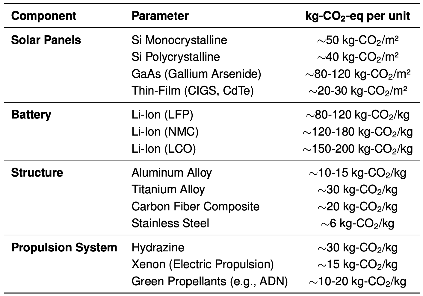
Table 2: Carbon Footprint of the Different Technologies. Basis for the Assessment of the Environmental Impact of High-Level Tradeoffs performed by the most impactful subsystems.
Then from these values and the mass of the different components, we can perform an estimation of the total carbon footprint and normalize it by using the boundary values (See figure 3). This framework allows us to extract a score for each subsystem and one for the entire system.

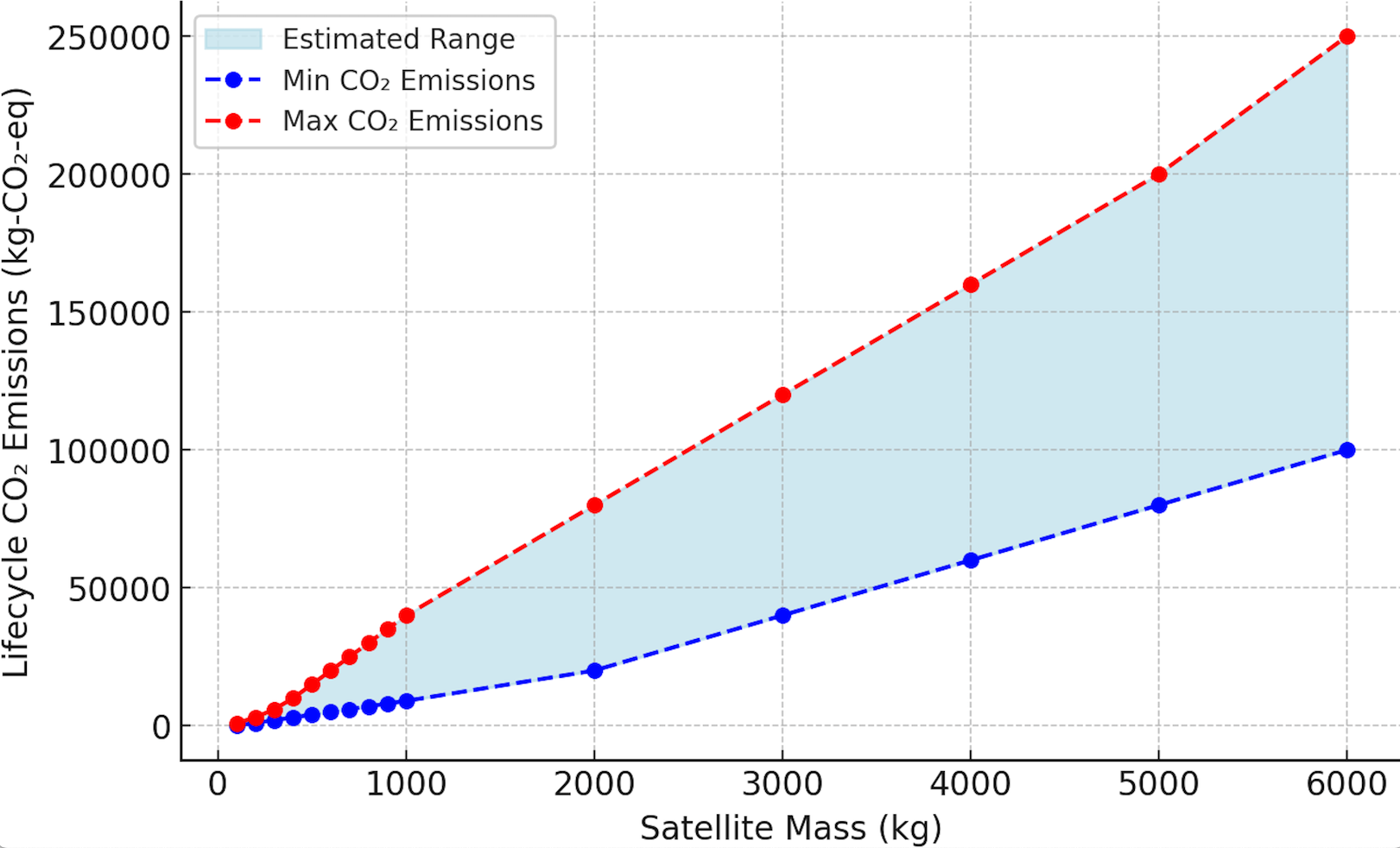
Figure 3: Illustration of the Tradespaces for the most impactful subsystems in terms of the Carbon Footprint (Left). On the right is shown the tradespace for the entire system, based on typical mass proportions of satellites at different scales (e.g. no propulsion for smaller spacecrafts). Boundaries defined by the extrema of Table 2. Own Figure.
Assessment of the safety of the mission
We desire to assess the safety of the overall mission. We define hazards as all undesirable events that occur from within the system boundaries, like the failure of a subsystem. In this part we want to identify all the parts of the system that may fail or behave in a way that was not intended. Then we want to analyse the behavior of the system that is caused by such an issue.
After having identified the hazards that may arise within the system. We want to identify whether mitigations exist to counteract undesirable behaviors. These mostly take the form of redundancy when it comes to hardware but may also be planned modes transition in given circumstances. The state of the system after the mitigation must be assessed to ensure that it is an effective one and that it is sufficient to ensure the survival of the system.
We use the following qualitative rationale to evaluate the safety of the system:
- 1: All the hazards that are identified have a mitigation that allows the system to keep a desirable behavior.
- 0.66: Most of the hazards that are identified have a mitigation that allows the system to keep a desirable behavior.
- 0.33: Most of the hazards have mitigations but these mitigations do not maintain the system in a desirable state.
- 0: The hazards are not mitigated.
In our case the main hazards are identified as follows, with the identified mitigations:
- System Propulsion Failure: Mitigation: redundancy by having 2 thrusters
- Power System Failure: Mitigation: redundancy by having multiple batteries and independent solar cells
- Communication System Failure: Mitigation: redundancy by having multiple antennas
Assessment of the resilience of the mission
We define resilience as the capacity of a system to provide value under unexpected conditions. These conditions are defined by external forces, which themselves constitute the main source of uncertainty for any system. Hence we want to characterize a case of degraded conditions that is possible and evaluate the performance of the system under these circumstances. The difference of provided value between the expected scenario and the degraded scenario will characterize how resilient the system is.
To characterize the environment of the system, we start by identifying the external forces of the system. These external forces are all the factors that may impact the function of the system but are out of the boundaries of the system. In our case, the main external forces are the debris and the solar activity.
After having identified the external forces, we want to model them to accurately define a degraded scenario. We could produce stochastic models, especially for the debris, but given the time constraints that are inherent to the design sessions, we will limit ourselves to simple scenario planning. This gives us the following:
EXT_FORCE_01: Debris Population
- Description: This represents the debris that may hit the spacecraft and cause damages.
- Normal: Description: Low debris density
- Degraded: Description: High debris density
- Critical: Description: Very high debris density
EXT_FORCE_02: Solar Activity
- Description: This represents the solar storms that may reach and affect the spacecraft.
- Normal: Description: Low solar activity
- Degraded: Description: High solar activity
- Critical: Description: Very high solar activity
Now that we have characterized the external forces of the system, we can provide a relevant description of degraded and critical cases for the system, and hence evaluate the outcomes of the system in these scenarios. Given the constraints imposed by the format of the project, we cannot quantitatively assess the outcomes of the system. Hence we will limit ourselves to a qualitative assessment as follows:
Normal Conditions
- System Outcome: Nominal
- Justification: Designed for this case
Degraded Conditions:
- System Outcome: Similar to normal conditions, cannot do much better with current technologies.
- Justification: No solar array (cells are on the spacecraft, not deployable), low aspect ratio, and thermal shielding.
Critical Conditions:
- System Outcome: The integrity of the spacecraft might be in danger.
- Justification: No solar array (cells are on the spacecraft, not deployable), low aspect ratio, and thermal shielding.
We then evaluate the resilience of the system using the following qualitative rationale:
- 1: The outcome in degraded conditions is similar as in normal conditions and outcomes remain desirable, hence the system is resilient.
- 0.66: The outcome is close between normal and degraded conditions, and all the functions remain compliant with the requirements.
- 0.33: The outcome is significantly different and falls below requirements, but the system survives.
- 0: The system fails completely and does not survive.
Mission Sustainability Score:
Finally, now that we have defined how we evaluate each aspect of the mission that is related to sustainability, we want to compute an overall score. Given that all previous scores are already between 0 and 1, we can perform a simple weighted sum to obtain a normalized score. The weights that were used are shown on figure 4.
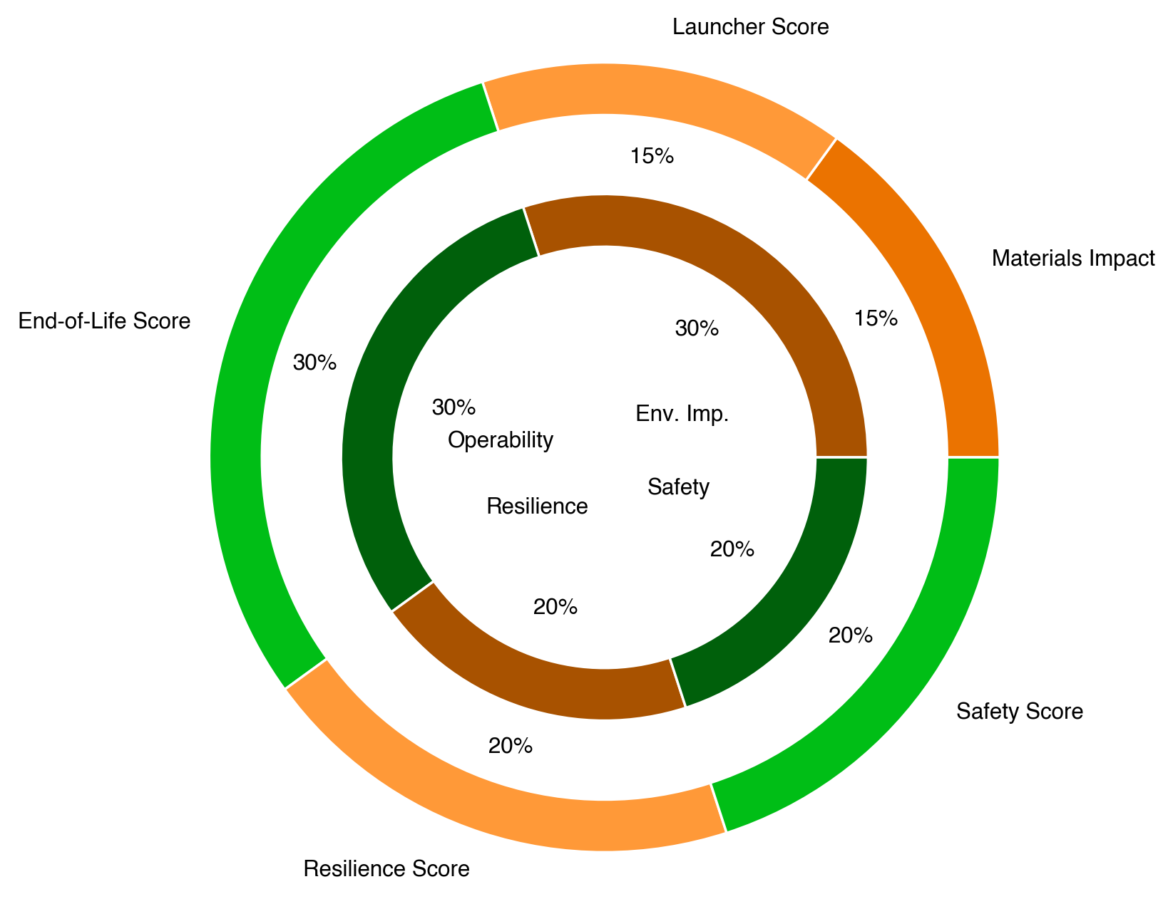
Figure 4: Weights used for the Mission Sustainability Score. Weights are allocated to the initial objectives and then conveyed to their associated scores (Explicit through matching colors). These weights are defined as such for the project but shall be adapted to stakeholder expectations. Own Figure.
[Results]
- Score for the material impact of the structure: 0.665
- Score for the material impact of the power subsystem: 0.83 (battery) and 0.25 (solar cell)
- Score for the material impact of the propellants: 0
- Score for the material impact of the entire system: 0.25
- Score for the atmospheric impact of the launcher: 1
- Score for the resilience of the mission: 1
- Score for the safety of the mission: 1
- Score for the End-of-Life strategy: 1
- Score for the overall mission: 0.91
CONOPS for End-of-Life strategy:
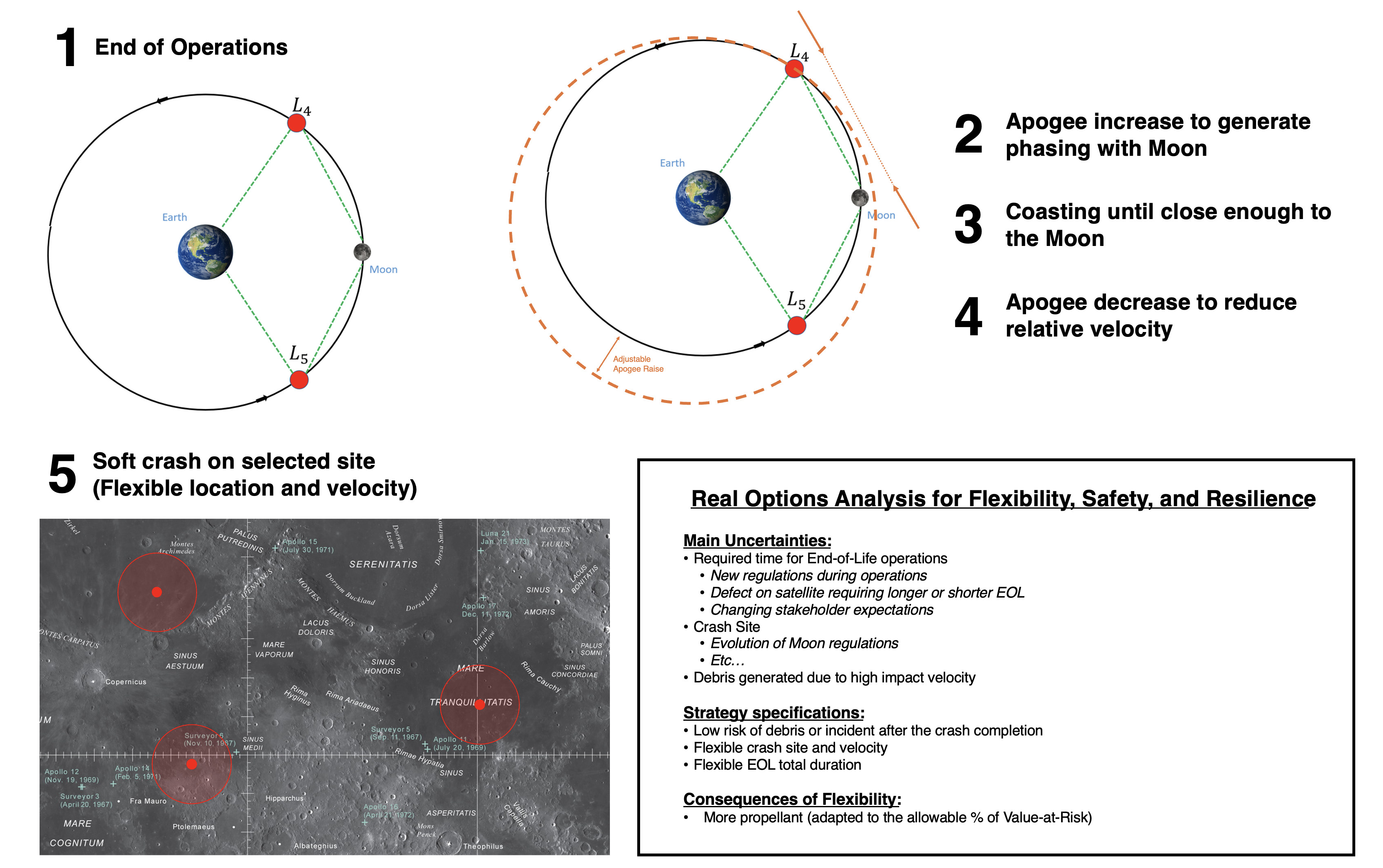
Figure 5: Concept of Operations for the End-of-Life Strategy of the mission. Real-Options are provided to recognize the uncertainty of this phase of the mission and how flexibility is integrated to ensure compliance with stakeholder expectations. Own Figure.
¶ Budgets (system level)
¶ Requirements:
- Shall support the other disciplines with their design
- Shall account for margins and contingencies according to project risk levels.
- Shall provide for flexibility to accommodate design changes and mission evolution.
- Shall be updated in response to technical changes, customer requirements or schedule updates.
¶ Tradeoffs:
A 20% margin was added throughout the design sessions in the budget to account for unknown or future changes. This ensures a safety margin up to launch if any changes are to occur during the following design changes.
The composition of each subsystem mass was taken from Space Mission Engineering: The New SMAD to determine the top-down mass budget. Considering the Ariane launcher with capacity of 3500 kg for a TLI and with a Launch Vehicle adapter of 500 kg, the resulting top-down budget was calculated for the 4 spacecraft in total in the following table.
| Subsystem | Top-Down [%] | Total Mass [Kg] | Mass for single spacecraft [kg] |
|---|---|---|---|
| Payload | 35 | 910 | 227.5 |
| AOCS | 6 | 156 | 39 |
| Structure and mechanisms | 24 | 624 | 156 |
| Propulsion (dry) | 7 | 182 | 45.5 |
| Power (inc.harness) | 17 | 442 | 110.5 |
| Thermal | 4 | 104 | 26 |
| CDH | 7 | 182 | 45.5 |
With this composition, the final mass budget was distributed and calculated as per the following table for a single spacecraft.
| Subsystem | Mass [kg] |
|---|---|
| Payload | 100.0 |
| AOCS | 37.4 |
| Structure and mechanisms | 55.9 |
| Propulsion (dry) | 7.6 |
| Power (inc.harness) | 92.6 |
| Thermal | 2.2 |
| CDH | 23.1 |
| Dry mass | 318.8 |
| Dry mass (20% margin) | 382.6 |
| Propellant mass (20% margin) | 72.0 |
| Wet mass | 454.6 |
| LV Adapter | 500 |
| Total Launch mass | 2318 |
As the Ariane 62 supports up to 3500 kg to a TLI, we are well within the available mass with a 33.8% margin.
¶ Risk assessment (system level)
Risk assessment was made by evaluating each subsystem and finding every failure point. Risks were identified and mitigation strategies were devised in the following table.
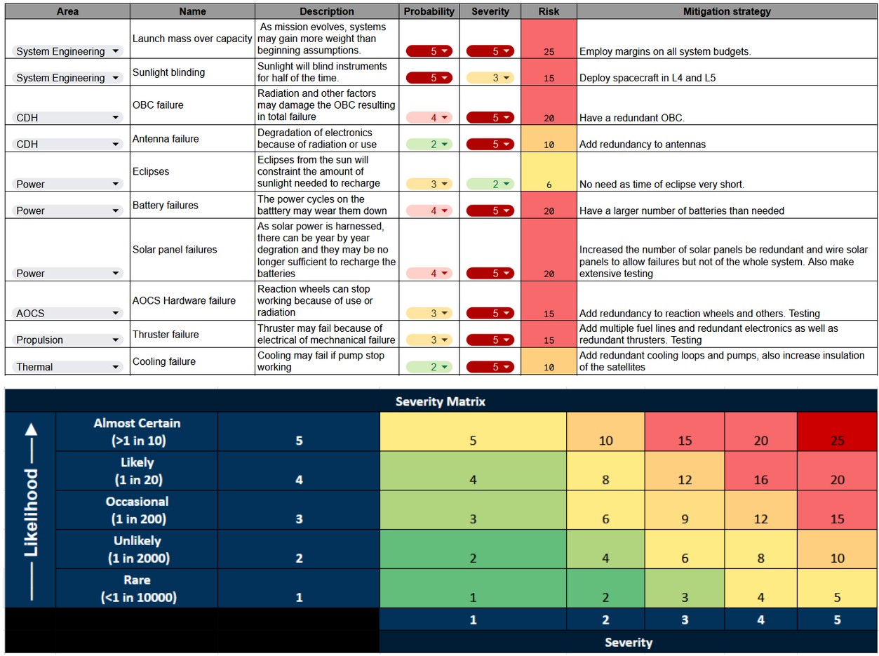
Probabilities go from 1 to 5 with 1 being the lowest and 5 being the most probable. Similarly, severity goes from 1 to 5, 1 being the least severe and 5 being the most severe. The risk is then calculated by multiplying both and color-coded to represent the scale of the risk.
Scale for the risk is as follows:
- 1-2: Very Low risk
- 3-4: Low Risk
- 5-8: Moderate Risk
- 9-12: High Risk
- 13-20: Very High Risk
- 21-25: Critical Risk
¶ Costs
Costs were not taken into account during this study.
¶ Post-Study Debrief
This study enabled the preliminary development of 4 satellites to fulfill the customers needs, i.e. to have an efficient object detection in Earth-Moon corridor system to support SSA in cislunar space. It was difficult to have a first draft and get every subsystem started, but once everyone had a better understanding of their goals, rapid iteration was possible. Every subsystem achieves a correct preliminary design, but future iterations shall consider the difference in progress made, as certain subsystems are more detailed than others, and the budget of mass for example differs sometimes a lot between the top-down and bottom-up approaches. A major trade-off made, impacting a lot of subsystems, was the type of propulsion used, mainly based on the trajectory needs. However, the trajectory was only decided using scientific publication and no simulation has been made yet.
A huge and recurrent lesson learned is the importance of good communication, as even with a good team communicating a lot, there were still some misunderstandings.
¶ Technical Lessons Learned
For general lessons learned about concurrent engineering, go to the useful_tips page (accessible to eSpace staff only).
[To complete during and at the end of the study: add below all technical lessons learned associated with the different disciplines/subsections]
¶ Trajectory Analysis
- Add lessons learned (Missing in the report)
¶ Configuration
- Configuration is a high-level role which overviews the full spacecraft and mission design. It is more involved than the system engineers when it comes to the engineering choices and tradeoffs on the spacecraft (the system engineers are more involved on the mission design).
- Being able to make a quick un-detailed CAD is really helpful to visualize the spacecraft, share this vision with the different members of the team, and calculate the positions to compute the center of mass and moments of inertia of the spacecraft.
- There is a big dependency between configuration and operations. In our case, choosing to have fixed antenna and solar arrays induced constraints to the operations (need for communication windows where the satellite can’t make operational observations).
¶ Payload
- For a preliminary study, it is very critical to have someone tasked on sizing the payload. It hardly makes sense to study the feasibility of a mission with no one working on verifying if the measurements wanted are possible to acquire, how much data they would generate, etc.
- In our case, a lot of very important uncertainties remained on how much data the payload would generate. This led to someone taking the responsibility to size the payload and devise an operational schedule to really assess the feasibility of the mission.
Some technical parameters (or the information to calculate these parameters) were contained in the references provided by the customers to the team.
¶ Structures & Mechanisms
- Primary lesson is the importance of early definition of launcher constraints. Parameters such as the adapter interface, envelope dimensions, static and dynamic loads must be clearly understood from the start to avoid invalid designs.
- Collaboration with the Configuration team is critical, especially for supporting the placement of subsystems that impact the design and choices of the structure. Having even a rough CAD early helps anchor structural assumptions and allows faster iteration.
- Many structural assumptions need to be conservative in early design stages. But, being too conservative can also lead to unrealistic mass budgets. A good balance is needed and a good collaboration with the System engineer is important to choose wisely when to change an assumption.
- The frequency requirements for lateral and longitudinal modes (e.g. 6 Hz / 20 Hz for cantilevered configurations) are difficult to verify without detailed FEM tools which are too advanced at this early stage.
- Constraining the mechanism to fixed subsystems is a good tradeoff for robustness and simplicity when it is possible.
- Mechanisms can fail if no redundancy is made. Here every system is based on a classical system to reduce risk but redundancy can be a wise choice to avoid a failed mission.
¶ Propulsion
In this chapter, I want to share the key lessons I learned during the design phase of our satellite mission. Working on such a complex project brings a range of challenges, which provide good opportunities to learn from.
One important lesson I learned is that you should not be afraid to rethink your work, even if you are already several sessions into the project. If, through discussions with other experts (such as during the mid-term presentation) or with your teammates, you come to the conclusion that your current solution is no longer the best one, it’s okay to throw it out and start fresh.
In our case, for example, after many internal discussions, we revisited our decision to use an electric propulsion system and ultimately switched to a chemical one.
- Lesson learned: Be open to changing direction if it leads to a better solution, even if the project is already underway.
Another takeaway is the importance of clean documentation. Calculations, designs, and results should always be well-organized. Especially in a project like this, where many people rely on each other’s work. This is where a software like COMET can help since we only had five sessions. Still, it took some time for me to get confident with the tool.
- Lesson learned: Good documentation is key to efficient collaboration.
Next, most of the processes in a complex system design are iterative like the calculation of the fuel mass. You often have to start with a rough estimate that can be far from the final value. But over time, as each subsystem is refined, the maturity of the overall mission increases.
- Lesson learned: Starting with “bad” values is necessary to reach a well-developed final system.
Finally, perhaps the most important lesson I have learned is the importance of good team dynamics. I believe our team worked well together. Open communication, asking questions, taking ownership of your responsibilities, and sharing results quickly are all critical in a project involving many people from different backgrounds. A team that collaborates effectively makes all the difference and can determine the success or failure of a mission.
- Lesson learned: A great team makes a great project.
¶ AOCS
- In the iteration process, the first step is definitely the hardest—starting from scratch is the biggest challenge. It's important to accept rough or even bad values at the beginning.
- I found the calculation sheets a bit too advanced for our level, so I didn’t really use them. Once mastered, the COMET-Excel combination is very effective, and I think I’ll use it again in the future.
- It's also essential to be open to others’ suggestions and discuss with different people, everyone comes from a different background, and that diversity can be very helpful.
- If I had to restart the project, I would begin by looking into previous missions to draw inspiration from them. In my opinion, I did it a bit late.
¶ CDHS
- It is essential to “prepare the design process” by focusing on crafting a strong requirements and interface baseline. Only then should the design process be initiated.
- The ESA calculation sheet was much too complex for the study. While the underlying models yield accurate results, such level of precision is simply too much for the initial design covered here.
- Most important of all is traceability. Initial mistakes from team members, myself included, ended up having a large impact on the design choices and selected components. Had we ensured that every member wrote their developments, calculations and hypotheses, such mistakes would have been avoided much sooner.
¶ Power
- One of the most valuable takeaways from working on the EPS was realizing that it is entirely possible to start from very rough, even simplistic, estimations and refine them progressively using course-based methods and external references. Despite not having taken any dedicated course in electrical power systems, I was able to build a meaningful and functional subsystem by focusing on engineering logic and structured assumptions. This was reassuring — deep prior knowledge isn't a prerequisite for producing useful subsystem work in early-stage design.
- Initially, I tried to model the system with too much complexity, particularly regarding mode transitions and temporal power profiles. It became clear later that a simple two-mode approximation (DAY and ECL) was both sufficient and robust for the mission profile. Had I recognized this earlier, I could have avoided unnecessary complications and saved time.
- In terms of design philosophy, I opted to build something functional, conservative, and robust, even if it meant oversizing components. The battery system, in particular, was significantly overdesigned — intentionally — to accommodate uncertainties and the late-stage update from the CDHS team regarding six daily communication sessions. While this led to a functional result, it highlighted how large margins can mask deeper optimizations that might be feasible with more coordination or time.
Tooling and Data Coordination
- A major source of inefficiency early in the process was my approach to COMET. I spent a lot of time trying to structure the EPS entries precisely, renaming and detailing every variable. In hindsight, COMET should have been used more pragmatically — as a place to store the key values only (mass, power, etc.). Had I taken a more minimalistic approach and directly requested each subsystem to input what I needed, I would have saved significant time and built my Excel toolset earlier and more confidently.
- Coordination with other teams sometimes happened late. The change from one to six communication sessions per day, for example, came very close to the end of the project. Fortunately, I had left enough margin in the design to scale the battery packs linearly, but this decision could have required a redesign in a tighter budget.
- The most impactful interactions occurred with the configuration, communication, and Trajectory teams, which helped refine constraints on array orientation and power budgeting.
What I Would Do Differently
If I were to restart the project:
- I would define the system’s operational modes as early as possible, even if oversimplified and choose a power model that matched the mission’s scale and simplicity.
- I would push to get a working first iteration loop (even if naive, and based on guesses) early in the process, then refine it instead of overengineering from the start.
- I would manage COMET entries as lightweight data points instead of trying to build structure around them too soon.
This experience also taught me that while the EPS is critical, its first-order behavior (especially in eclipse-free missions with good Sun exposure) can be addressed effectively without electronic detail, as long as physical and mission-level constraints are respected.
For future missions, it would be valuable to refine the EPS by incorporating more detailed electronic modeling (e.g. regulators, PCDUs, failure modes) and by exploring dynamic power profiles in more complex orbital environments or under stricter mass constraints.
¶ Thermal
If I had to do this again, here’s how I would do it:
- Review literature like SMAD or Spacecraft systems engineering about spacecraft thermal analysis
- Review the past Concurrent Engineering course projects to get an idea of how they worked (I didn't...)
- Create some basic parameters in COMET, and learn how to use your teammates parameters
- Determine operating conditions of the spacecraft, working together with Power and Trajectory Analysis
- Get to know the spacecraft geometry with Configuration and Structure, and discuss possible coating options
- Create a first basic thermal model, first on paper and then on the software you like (you can then translate it into VBA code for Excel and COMET), to estimate the thermal control system and its mass
- Refine or trash the model as the team progresses further. In both cases, make your code clean and understandable to modify it efficiently
¶ Space sustainability
-
Overall
The mission being a typical “old space” case reduced the challenge of integrating sustainability as a domain of expertise, which was good for a first test. Now that the role has been defined and iterated upon, it would be interesting to test it on a case of New Space (e.g. SATCOM Constellation) with a larger tradespace. -
Team
On the team side, an important lesson is that this project is a course, and the students have very different backgrounds. Once a baseline design / set of parameters has been defined, these differences in background start to fade, but in the early design sessions, this creates a real bottleneck. Hence having a robust mitigation plan (e.g. predefined values, given in case of emergency) to make sure that the design’s first iteration does not get too long, or that students do not get stuck in the very early stages would probably allow to go much further in the last sessions (where real improvements arise system-wide). -
Software
First Activity Browser was considered to perform the high level life cycle assessment but it had to be abandoned during the project for AI generated data. It was identified that Activity Browser is not adapted for rapid decision making and especially for high level tradeoffs. Hence a lesson that we can define is that a tool for technology choice should be created to enable an efficient and reliable decision. Currently, AI generated tools were effective and showed what kind of tools were needed, but the reliability of the data needs to be assessed. -
Central Repository
COMET was hard to use in the context of the sustainability domain and most of the information that was needed was collected via oral interactions. Indeed, information like the selected technologies could not be collected (only values like mass), and other crucial parts like CONOPS were not available on COMET. Hence it would be interesting to explore tools that allow us to share more than simple values (images, diagrams, etc…). The main lesson learned in this case is that human interactions constitute a very important part of the concurrent engineering process and that an active effort should be made toward it. -
Process
An important point that could be noted throughout the sessions is that although multiple pieces of information are required to perform some calculations, they do not come at the same time. Hence it is important to plan for these cases and perform educated guesses on possible values that will “fill the gaps” until more information. It is very important because some values come very late in the process and if no output is being produced from the sustainability until then, the impact on the system becomes very reduced. Therefore these “educated guesses” shall be planned in advance rather than on the go, like a risk assessment of the concurrent engineering process.
¶ Systems Engineering
As a system engineer, it is important to keep an eye on the overall mission and not only look at each subsystem. Communication between subsystems is a key element to systems engineering and getting everyone on the same page with the same information is crucial.
Budgets:
- Very important to have a heritage mission to get an initial mass guess of the whole spacecraft.
- Literature is a good basis for the percentages of the mass budget.
Risk assessment:
- It is important not only to look at technical problems of the spacecraft but also to look at what other external factors could go wrong like going over budget or exceeding timeline expectations.
- COMET is a powerful tool to consolidate all data between every subsystem but it is hard to use and it is important to get a know-how before starting the design process of the mission.