¶ Concurrent Engineering Challenge 2022
DUMBO - DUal Moon Beam Orbiter
¶ Report Status
Version: I01
Reviewed by: David
Review date: 22/07/2022
Review status: ✅DONE
As part of the 2022 ESA Concurrent Engineering Challenge (CEC), a team of students at EPFL, together with another two teams based at ESA Education Training Centre (ESEC-Galaxia) in Belgium and at the University of Luxembourg, conducted a week-long study to design a remote prospecting mission in lunar orbit.
The following contains all the relevant informating resulting from this study, from the context and mission objectives to lessons learned.
For a list of terms and acronyms often used, check the Glossary section.
This study was performed at eSpace Concurrent Design Facility by the following team:
| Name | Affiliation | Role |
|---|---|---|
| Denis Galagan | eSpace | Team Leader/Facilitator |
| Mathieu Udriot | eSpace | Team Leader/Facilitator |
| Thomas Manteaux | EPFL | Attitude & Orbit Control (AOC) |
| Quenting Delfosse | EPFL | Communications & Data Handling (CDH) |
| Mehdi Krichen | EPFL | Configuration |
| Julien Moreau | EPFL | Power |
| Vincent Python | EPFL | Propulsion |
| Louise Cayroche | EPFL | Structures & Mechanisms |
| Kevin Marangi | EPFL | Structures & Mechanisms |
| Théotime Lemoine | EPFL | Thermal |
| L'Emira Emma Chehab | EPFL | Trajectory Analysis |
Under the responsibility of:
S. Hamel, eSpace, Study Coordinator
D. Rodríguez, eSpace, Study Coordinator
With the technical support of:
N. Cardines, eSpace, Systems Engineering Support
M. Juillard, eSpace, Systems Engineering Support
H. Koizumi, University of Tokyo, Systems Engineering Support
C. Norhadian, eSpace, Logistics & Admin Support
¶ Introduction
¶ Background
From April 4 - 8, 2022, an interdisciplinary group of EPFL students took part in the annual Concurrent Engineering Challenge (CEC). The CEC is a week-long event organized by the European Space Agency’s (ESA) Education Office and Systems and Concurrent Engineering Section intended to teach graduate students the principles of concurrent design for space missions and to support the development of new concurrent design facilities throughout Europe.
For eSpace, the CEC'22 was a vehicle to re-inaugurate activities associated with concurrent design at EPFL as well as an opportunity to revise the present use and configuration of the center's forsaken concurrent design facility (CDF).
¶ Objective
The objective of this study is to design a mission involving a mothercraft and two cubesats to remotely prospect the poles of the Moon in search of water ice using bi-static reflectometry.
¶ Scope
The mission is envisioned as a distributed space system in lunar orbit consisting of a single, larger satellite (aka the "mothercraft") and two cubesats. The mothercraft would be used as a signal transmitter of the bi-static reflectometry system; while the two cubesats would work as signal receivers. This mission concept provides increased operational flexibility and redundancy. Reflectometry provides advantages through high sensitivity, low-gain (high field of view), and moderate date volume.
As part of this study, only the mothercraft shall be designed. The two cubesats must be simply used as inputs to the study and shall be considered as dummy payloads.
¶ Executive Summary
As part of ESA CEC 2022, three student teams supported by experts and located at ESEC, the University of Luxembourg, and EPFL took on the challenge to design, in less than a week, a lunar remote sensing mission to characterize water ice in the polar regions of the Moon via the use of bi-static reflectometry.
¶ Study Objectives
Water is one of the most sought-after resources in space. Due to its multiple uses, from the production of propellant and breathable oxygen for astronauts to drinking water and radiation shielding of high energy particles, water is driving the selection of prospective areas of exploration for governmental agencies and private corporations alike in the upcoming years. Water ice also holds unique scientific value providing information on the history and chemistry of the inner Solar System (trapped Solar wind particles).
Since the 1960s water in the form of ice has been suspected to be widely located in lower temperature regions in the lunar poles. Due to the small inclination of the Moon’s equator to the ecliptic (1.5°), these regions are barely lit by sunlight or even remain permanently in shadow, acting as “cold traps” for volatile compounds. As a result of the findings made by the LCROSS and LRO missions, the lunar South Pole is being considered a prominent destination for future exploration missions. The objective: to validate in-situ de existence, amount, and distribution of water ice in the polar regions of the Moon.
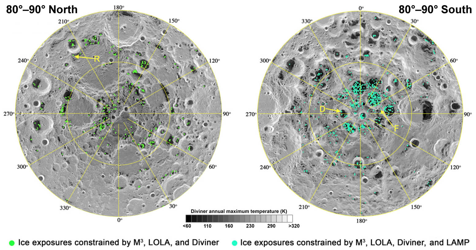
In this context, the mission primary and secondary objectives are:
- To perform reflectometry with cubesats of the lunar polar regions to detect, quantify, and map water ice resources.
- To demonstrate the applicability of a distributed satellite system (mothercraft and two cubesats) for remote sensing missions.
¶ Bi-static Reflectometry
Similar to how on Earth oceanographic and cryospheric properties can be measured from orbit by means of GPS reflected signals, bi-static reflectometry can be used to detect, quantify, and map water ice deposits on the polar regions of the Moon.
Bi-static reflectometry takes advantage of the signals generated by the mothercraft ("the transmitter") whose reflection on the lunar surface are then measured by the the two cubesats ("the receivers"). The time delay and frequency change between the original signals from the mothercraft and the receiving signals by each of the cubesats can provide valuable information on the state and composition of the lunar surface.
¶ Requirements and Design Drivers
The mission requirements and main system requirements, as provided by the engineering team at ESA prior to the study, are presented in the following table.
| Ref | Requirement |
|---|---|
| MIS-M-001 | The mission shall use Ariane 6 or Vega-C |
| MIS-M-002 | The mission shall measure water ice quantity at the Lunar Polar regions |
| MIS-M-003 | The science phase shall be 1 year |
| MIS-M-004 | The mission shall be launched before 2027 |
| MIS-M-005 | The mothership shall carry and deploy 2 CubeSats in low Lunar orbits |
| MIS-M-006 | The mission shall use a mothership for data processing and as communication relay to Earth |
| MIS-M-007 | The mission shall use bi-static reflectometry with: a) a signal transmitter on the mothercraft and b) a receive on each of the cubesats |
Mothercraft design drivers
- P-band and S-band transmitter
- CubeSat deployer
3U CubeSats design drivers
(out of scope for the study )
- P-band and S-band receiver
- Mass: 5 kg (per CubeSat)
- Data rate: 2 Mbit/s (uplink)
- Generated data volume: 640kbit/s (nadir pointing receiver)
- Mass memory: 256 MB
- A minimum duty cycle of 1/3 of the orbit for operation of the main passive reflectometer payload has been considered necessary.
¶ Mission
A summary of the outcome of the study is presented in this section.
The following figure illustrates the overal concept of operations (CONOPS) for the mission, dubbed DUMBO, or DUal Moon Beam Orbiter.
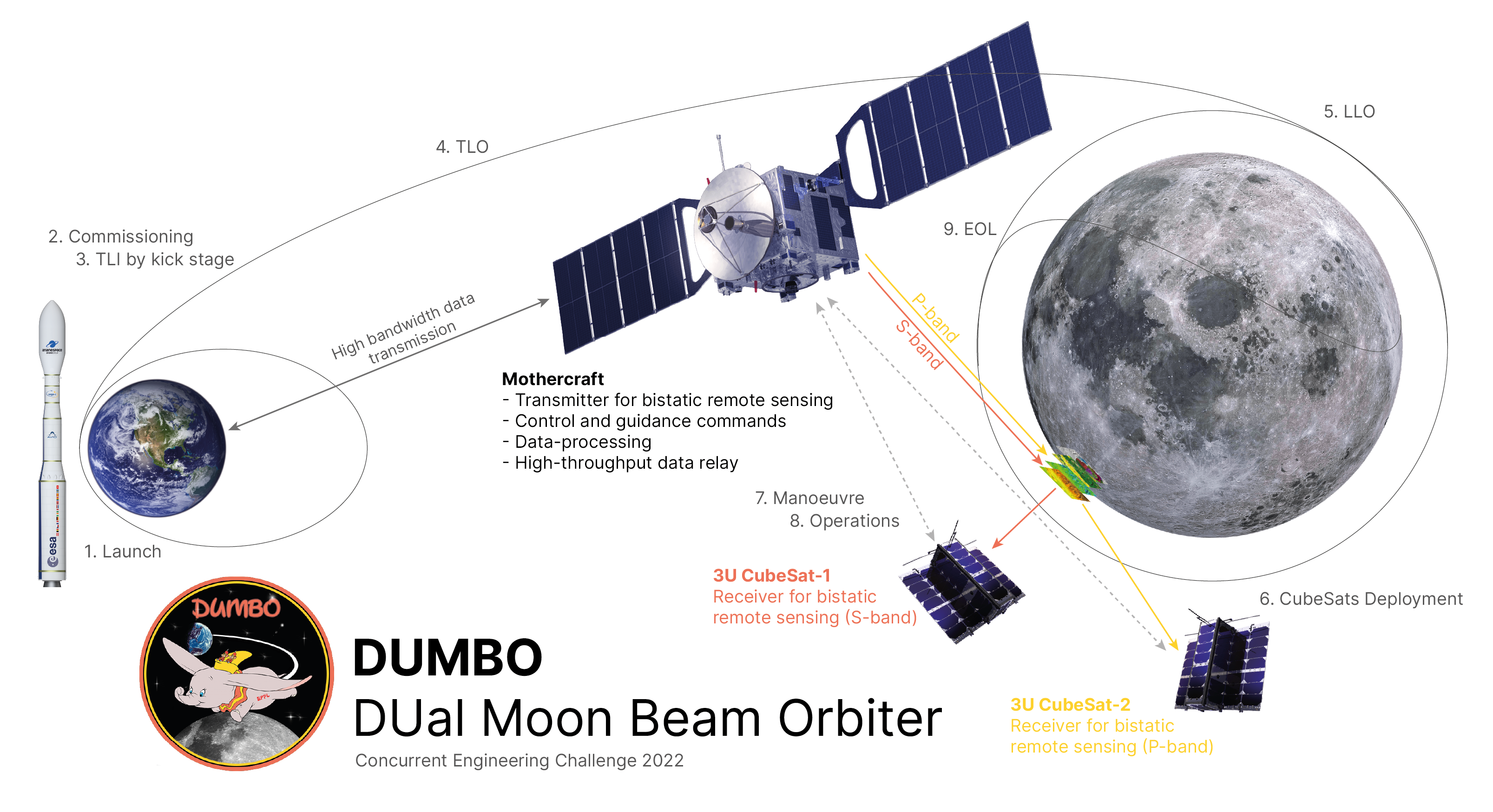
A Vega C launcher brings the mothercraft into a 5-day trajectory to lunar orbit. After a lunar orbit insertion burn, the mothercraft is placed in low lunar orbit, 100km above ground where the two cubesats are deployed. The total delta-v required for these maneuvers is 1.04 without taking into account the trans-lunar insertion (TLI) performed by the kickstage. Total propellant mass without TLI yields 172.2 kg.
The mothercraft has been designed with two main configurations: folded and deployed. Overall mass of the mothercraft is 1323 kg (including kickstage and adapter). Power is provided via steerable solar panels providing 800 W during sunlight. During eclipses, 590 W·h batteries provide more than 355 W and can be also used for short periods of time in other modes of operation. Internal structure is made of 3-mm thick aluminum honeycomb sandwich panels. Two standard cubesats deployment mechanisms are used for deployment of the payloads. The spacecraft is propelled by 4 Bradford ECAPS 200 N HPGP thrusters and its attitude is controlled via 8 Bradford ECAPS 0.5 N HPGP thrusters and 4 3-axis 4Nms reaction wheels. All thrusters make use of the same LMP-103S propellant. For telemetry and telecommands, a fixed X-band atenna dish is used. S-band and P-band patch antennas are used for the transmission of the bi-static signals.
Further details on the mission and the design of each subsystem are presented in the following results section.
¶ Results
From the high level requirements described above, each subsystem translated some into lower level, more precis requirements applicable to their design and operation. The subsystem requirements are listed at first and the final solutions, retained after several iterative loops, are explained.
¶ Trajectory Analysis
Requirements:
- Shall provide a trajectory to correctly enter the lunar orbit and its duration.
- Shall place the mothercraft on a final circular orbit at 100 km altitude in low lunar orbit.
- Shall compute a disposal manoeuvre for the end of life.
- Shall compute the delta-v required for the entire lifetime.
Tradeoffs:
- Use of Ariane 6 or Vega-C.
- Definition of the low lunar orbit (LLO) for the mothercraft.
Justifications:
- Ariane 6 was first considered but the mass of the spacecraft was far lower than the launcher performance. This would have meant a really expensive mission (in price per kilo) in the case of a dedicated launch, or a much more complex trajectory management in case of a rideshre. The latter option was also discarded because with a rideshare, it would have been highly likely that the spacecraft would have been separated from the launcher on GTO, and reaching the Moon from GTO is a challenging task.
- The Cubestas operational orbits were defined in the mission requirement (LLO: 100 km, 86 deg inclination). For a simple pattern of observation windows, it was decided to stay on the same orbit.
Results:
The final trajectory is based on the performance of the Vega C launcher. Vega C is able to insert the mothercraft and its payload on an elliptical orbit (5700kmx250km) around the Earth. By performing a trans-lunar insertion (TLI) burn and then a lunar orbit insertion (LOI) burn with its kick-stage, the spacecraft is able to raise its apogee to 400'000km and then circularize around the Moon in low lunar orbit (LLO). The duration of the trip to the Moon's orbit is around 5 days.
Around the Moon, at 100km in low lunar orbit, the orbit duration is 7065 sec (~2h). The cubsats will be injected on the same orbit and the mother craft will manoeuvre to fall back in terms of true anomaly to have an good angle to perform the measurements.
At end of mission, when no more fuel is available for station-keeping or another constraint prevents the science objectives (that shall be at least 1 year after commissioning), the spacecraft is deorbited and crashes on lunar soil.
The total Detla v budget is shown in the table below. A contengincy on the propellant mass will be added at system level in the system budget section.
| Manoeuvres (burns) | Delva v [km/s] | Propellant mass [kg] |
|---|---|---|
| TLI (performed by kick-stage) | 1.866 | kick stage |
| LOI | 0.880 | 134.5 |
| Station keeping | 0.090 | 10.9 |
| Deorbit | 0.023 | 2.8 |
| Total (w/o TLI) | 0.993 | 148.2 |
| Sub-System contingency | 5 % | - |
| Total (w/o TLI) with contingency | 1.04 | 172.2 |
¶ Configuration
Requirements:
- Shall identify and create the configurations of the spacecraft
- Shall identify subsystems' needs and define the location of their equipement in the satellite
- Shall determine the MoI and the CoG of the spacecraft
Results:
Starting with the folded configuration (while in the fairing and before deployment and commissioning). The spacecraft, its large dish antenna, solar panels and other equipments are on top of the kick-stage (see structures and mechanisms). For this configuration, it is important to have a compact, inactive spacecraft, with a balanced weight distribution.
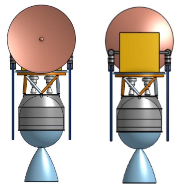
To be able to deploy the solar panels, the deployment mechanisms shall be clear of any interference.
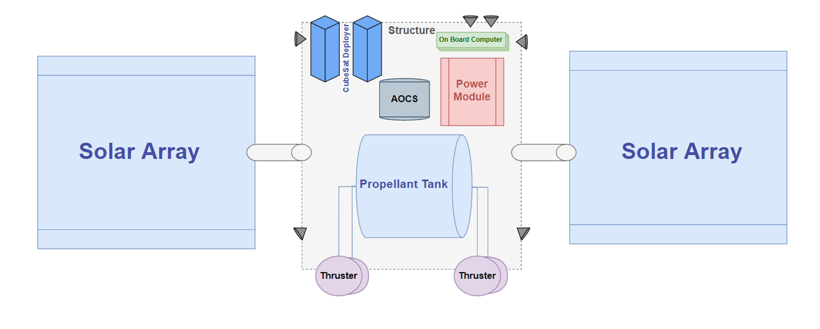
The main structure is a cubic box 0.7 m wide. In the deployed configuration, the CoG is not exactly at the center of the box, it is offset by about 100 mm on two axes and 20 mm in the remaining axis.
At the center of gravity, the moments of inertia are 22, 74, and 79 kg·m2 in the x, y and z axis, respectively.
A 2D diagram showing approximately the distribution of the subsystems inside the deployed configuration is shown below.
¶ Structures & Mechanisms
Requirements:
- Shall estimate the loads applied depending on the configuration and deduce the structural mass
- Shall define separation mechanisms for companion spacecrafts
- Shall identify all necessary mechanisms like solar array drives, etc.
Tradeoffs:
- Thickness of the walls to support loads and addition or not of stringers (support beams).
- Inclusion or not of deplyoment mechanisms for different subsystems.
Justifications:
- ???
- Solar arrays have to be controllable to maximize energy harvesting. Justification for the antennas is coming for the [CDHS](/glossary#c subsystem.
Results:
The external structure (the cubic box described above) is made of aluminium, 3 mm thick, to stand the loads during launch. This makes up a mass of 16.4 kg. It is suggested to use sandwich panels (aluminium skin on the side of a honeycomb structure) for the internal structure, holding the equipment. This material is light and yet very resistant.
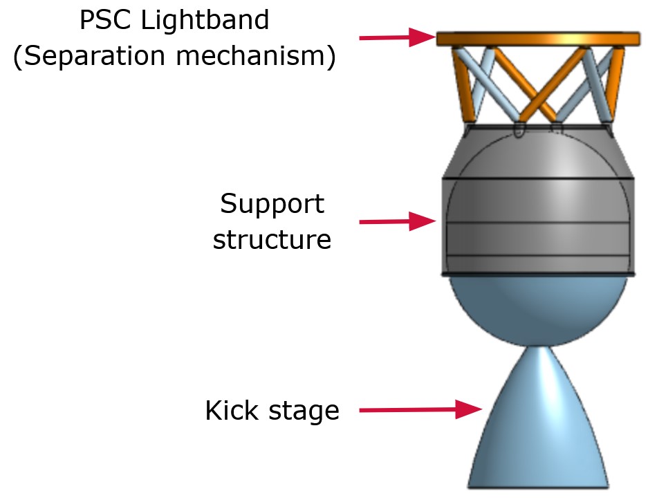
Several machanisms have been identified: the solar panels shall be deployed and orientable. To accommodate the addition of the kick-stage and get rid of it after its burn, a separation mechanism connects it with the main spacecraft structure as shown in the figure below. Two standard cubesat deployment mechanisms are also needed to inject the payloads.
The x-band dish antenna is fixed. The s and p-band antennas are patch so they cannot be moved neither.
¶ Propulsion
Requirements:
- Shall define the propulsion system and the propellant type
- Shall select the actuators for attitude control
Tradeoffs:
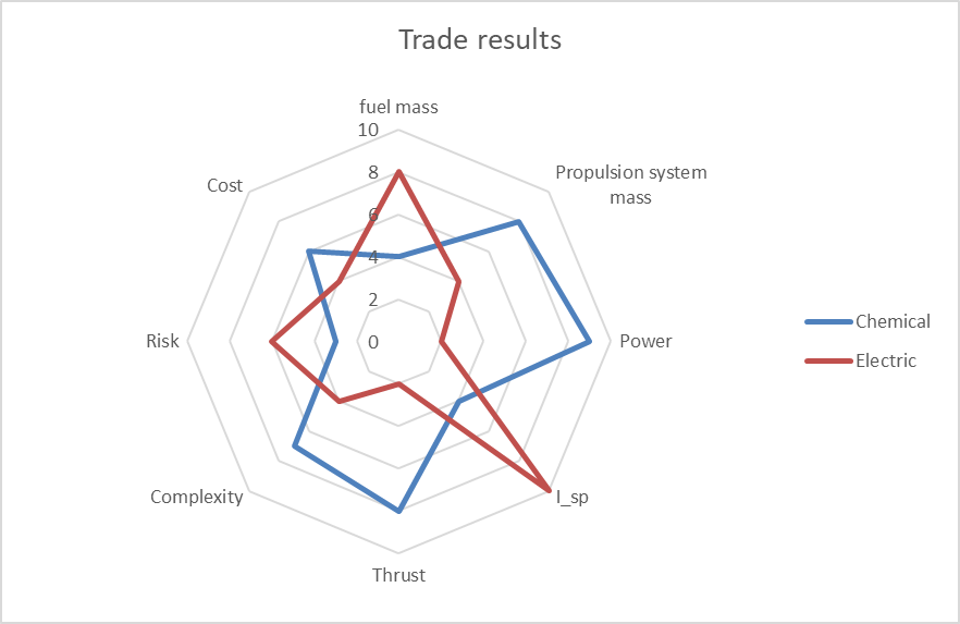
- Electrical versus chemical propulsion.
- Then, chemical propellant type.
Justifications:
- Chemical propulsion was found more adapted to the mission's requirements.
- First hydrazine was investigated due to its heritage (propellant used on the Lunar Reconnaisance Orbiter (LRO) mission). But eSpace is committed to sustainability in space and in the space sector. Therefor a mission designed around core values for space debris mitigation and using novel technologies like the greener LMP-103S propellant with adapted hardware (Bradford ECAPS)
Results:
For simplicity, it was decided to use the same propellant for the main propuslion system than for the AOCS. The choice was made to go for a "green" propellant, LMP-103S. This chemical monopropellant was chosen instead of hydrazine for several reasons. Hydrazine might be banned in the coming years because of its toxicity. LMP-103S has two advantages: 1) it has a higher Isp and 2) it is more dense. On the flip side, LMP-103S is so far the more expensive alternative due to lack of demand for mass-production.
The kick-stage to perform the TLI is a STAR 30 BP.
The main propulsion module is made of 4 Bradford ECAPS's 200N HPGP thrusters. 8 Bradford ECAPS's 0.5N HPGP thrusters are used for the AOCS (see below).
Other elements of the propulsion system have been identified but not precisely selected like: pressurant tank, pressure transducers and regulator, fill, drain, and Latch valves, pyrovalves, filters.
The total mass of the propulsion subsystem is estimated at 30.4 [kg].
¶ AOCS
Requirements:
- Shall choose equipment based on required pointing and rotation rate requirements and thrust/ delta-v requirements
- Shall list required sensors to perform attitude control with required accuracy
Tradeoffs:
- Technology used for attitude control (thrusters versus reaction wheels).
- Type and number of sensors to embed on the spacecraft for accurate and reliable measurements.
Justifications:
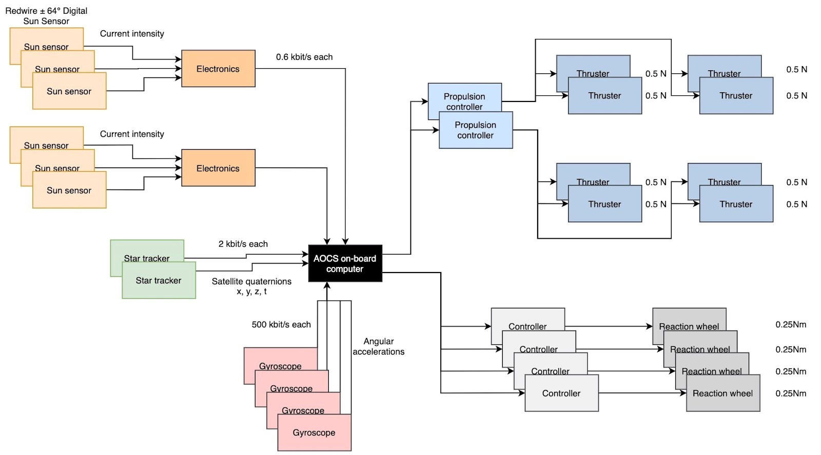
- A combination of thrusters and reaction wheels will be used. The former will be able to desaturate the latter. The whole design is based on the assumptions that a maximal of 7.21E-5 Nm is applied to the spacecraft in LLO. No magnetic torquers could be used since there is no magnetic field around the Moon.
- Sensors and their justifications are given below.
Results:
| Actuators | Amount | Rational | Limits | Performance | Redundancy | Reference |
|---|---|---|---|---|---|---|
| Reaction wheels | 4 | 3-axis stabilization | Life of sensors, wheel bearings | 4 Nms | Hot | Ref |
| Thrusters | 8 | Orbit manoeuvres, momentum damping | Propellant mass | 0.5N | Cold | Ref |
The same table is provided with the sensors below:
| Sensors | Amount | Rational | Limits | Performance | Redundancy | Reference |
|---|---|---|---|---|---|---|
| Sun sensors | 6 | Initial vehicle attitude, coarse attitude data | Power, radiation | +/- 0.25° | Cold | Ref |
| Star Trackers | 2 | Absolute altitude | Power, radiation | +/- 0.002° | Hot | Ref |
| Gyroscopes | 4 | Rotational rates | Power, radiation | +/- 0.3°/h drift | Hot | Ref |
¶ CDHS
Requirements:
- Shall define the equipment needed based on the data rates needed for ground station contact and inter satellite links
- Shall define the on board data handling hardware needed (memory mass, etc.)
- Shall embark a s-band and a p-band transmitter for science above the lunar poles (see section about bi-static reflectometry)
Tradeoffs:
- Storage margin and transmission data budget versus data produced.
- Tansmission margin versus antenna availability and storage.
- Choice of the ground station.
Justifications:
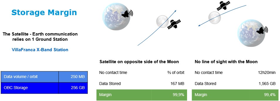
- The dimensions are based on the identified data rate produced by the scientific payload and by the telemetry (housekeeping information) of 250 MB per orbit (with a sampling ratio of 10).
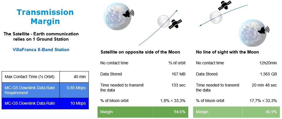
- There are constraints for when it is possible to transmit back to Earth. It is assumed 1/3 of the orbit can be used for data transmission back to Earth while the spacecraft flies over the lunar polar during two times 1/6 of an orbit.
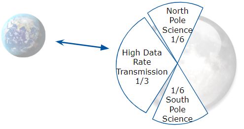
- New Norcia X-Band ground station (GS) is in fact used for deep space mission thanks to its huge antenna dish, it is thus really expensive to use. The alternative is to use the VillaFranca X-Band GS with an increased OBC storage capacity (256 GB).
Results:
The hardware selected for the subsystem is presented below.
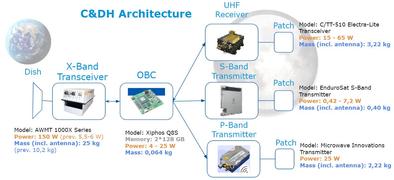
The margins are shown to be sufficient in the figures below.
¶ Power
Requirements:
- Shall gather power needs and operation depending on system modes from all subsystems
- Shall design equipment based on the total power budget in the satellite
- Shall include enough battery capacity to survive in nominal mode during night (identify worse case)
Tradeoffs:
- Battery sized for maximum consumption in worse-case mode (eclipse) versus reduce consumption during this phase.
- Battery capacity sized by peak power consumption versus designed for supporting maximum throughput and have capacity to answer average demand.
Justifications:
- “One time events” (i.e CubeSat deployment) were not considered in the budget to size the batteries and the power system. They are covered by the capacity margin of the batteries.
- The peak power consumption happens in maneuvering mode due to the use of the main propulsion. But it last maximum 200 seconds, so equivalent to 70 W.h of capacity. Still the system has to be able to provide this peak power without damaging the cables, batteries, and equipment. The driving requirement for the sizing of the batteries is te nominal eclipse mode whihc last longer.
- The solar panels shall cover the power needs during sunlight and generate enough to recharge the batteries too. The batteries capacity and the nominal sunlight power consumption set the requirements for the solar cells.
All values in the budget table below are given in Watts [W].

Results:
Batteries:
- 2 batteries used for redundancy
- Total of 2 x 590 = 1180 W.h
- Total weight of 8,8 kg
- Dimensions : 2 x 269x167x67mm
- Operating temperature : -10 to 55°C
Solar cells:
- Minimum efficiency of 29.5%
- 500 solar cells, margin of 10%
- 3,65 m2 over 2 solar arrays
- Mass of the cells: 3 kg
- Mass of the array structure 19.5 kg (using area density of 4.5 kg/m2)
Other elements estimation (based on VPCDU-1 device)
- Power unit controil: 10kg
- Regulator/Converters: 10 kg
- Wiring: 4 kg (corrected in mass budget, see below)
Power system total mass is 60 kg. Solar arrays provide up to 800 W during Sunlight (equipment + batteries). Batteries provide more than 355 W during eclipse and can be used for short periods of time in other modes.
¶ Thermal
Requirements:
- Shall identify operational and survivability temperature range for all equipment
- Shall define the thermal equipment required to survive during worse case
- Shall help configuration with the placement of equipment with difficult thermal requirement
Tradeoffs:
- Use of passive versus active thermal control strategies.
- Dimensioning to keep all elements in their operational or survivable temperature range in worse-case (eclipse).
- Use of protective thermal layer against thermal load generated by the main propulsion system during manoeuvering.
Justifications:
- First passive strategies are used for the whole spacecraft and active elements are added to meet specific requirements of equipments that are particularly exposed or critical.
- The nominal operating temperature of the spacecraft is defined between -5°C to 40°C, and the maximum and minimum electrical power consumed (in nominal and safe mode respectively) are know from the power subsystem.
- The solar panels have an operating temperature between -180°C and 95°C.
- The maximum eclipsed time is of 185 minutes.
Results:
Coating:
- 5 mils Aluminium backing Kapton Film from DuPont™ (Kapton® HN 127)
- Emissivity: 86%
- Absorptivity: 46%
- Around 0.5 kg
Insulation layer between the thrusters and the spacecraft:
- To protect from thermal load of 1266 W for around 200 seconds.
- Low Thermally Conductive Silicone elastomer (CV1-2964 from NuSil (Space Grade)), 0.95 W/(mK) of thermal conductivity.
- Thickness of 10mm, mass around 2 kg, gives a thermal SF of 1.37.
Active thermal system for the solar panels:
- 30 W to heat minimum temperature from -194°C to -166°C.
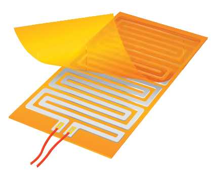
- Kapton adhesive heating patch circuit between the substrate and the solar cell. With:
- 8 Thermocouples sensors (4 for each solar panel)
- 4 Passive Thermostats (To control the heating)
- 2 DC/DC Converters (To go to 120 V and 250 mA)
- Around 3.9 kg.
Example of a Kapton adhesive heating patch circuit below.
Active thermal system for the eclipse mode:
- Estimated 26 W of power.
- Kapton adhesive heating patch circuit between the substrate and the solar cell. With:
- 12 Thermocouples sensors (3 / Battery + 4 / Sensors & OC + Others)
- 2 Passive Thermostats (To control the heating power)
- 2 DC/DC Converters (To go to 120 V and 250 mA)
Total weight of the active thermal system is around 2.1 kg.
¶ Budgets (system level)
Requirements:
- Shall support the other disciplines with their design
- Shall create a system mass budget, check assumptions and consitency of the subsystems
Tradeoffs:
- The contingency percentage added on top of each subsystem's results.
Justifications:
- Contingencies were added depending on the confidence one had in the design of the subsystems. The contingency for the power subsystem is still quite large because it includes more mass for the harnesses and cables. The one for thermal is also large because the design choices ended with a very low mass and large uncertainties about the equipment that could really be implemented to heat the solar panels.
Results:
The contingencies droped during the week as the design got more and more precise. Especially the one for structure which went from 100% to 20% thanks to more rigorous calculations of their mass.
| Subsystem | Contingency [%] | Mass w/ contingency [kg] |
|---|---|---|
| Thermal | 50 | 16.7 |
| Payload | 20 | 18.96 |
| Power | 40 | 83.65 |
| Propulsion | 15 | 34.96 |
| Structure & mechanisms | 20 | 175.28 |
| CDHS | 20 | 30.07 |
| AOCS | 10 | 18.12 |
An addition contingency of 20% is added at system level because it is still an early study. This brings the total mass to 453,29 kg. From the propulsion, one knows the propellant mass is 172.2. 20% margin is also added there to account for spin and despin of the spacecraft before and after the use of the kick stage, to get 206.64 kg.
| System | Mass w/ contingency [kg] |
|---|---|
| Spacecraft wet | 659.93 |
| Kick stage | 543 |
| VAMPIRE 937 Adapter | 120 |
For a total launch mass of 1323 kg, this compared to the Vega-C performance of 1700 kg to an orbit of 5700x250 km, i=6°. This means our system can be launched by Vega-C to the required orbit!
¶ Technical Lessons Learned
For general lessons learned about concurrent engineering, go to the useful_tips page (accessible to eSpace staff only).
¶ Trajectory Analysis
- Delta v computations had to be done several times for different mission concepts. There is a need to use trajectory analysis software (see the software index) for computations and to generate figures.
- There are several ways for mission concepts to go to the Moon: either by a direct Lunar Orbit Insertion (LOI), performed by the launcher, or via a Trans-Lunar Injection (TLI) burn performed by the spacecraft propulsion (in this case an additional commercial kick stage, see the propulsion section).
- Do not add large margins on the Delta v calculations as the value will be used in an exponential function to find the propellant mass. Instead, leave it to the propulsion system and the systems engineers to add margin on the masses.
¶ Configuration
- The subsystem shall identify the main configurations since the beginning of the study (spacecraft during the launch in the fairings, during deployment, in operations, if it is released or it docks on orbit, etc.). Each configuration has different requirements.
- Volume [m3] shall be a parameter in all subsystems on the CE software. It is useful for the configuration subsystem and to compute estimate of inertia for AOCS.
- Configuration needs to be in constant discussion with other subsystems.
- An early CAD is not the priority but it’s nice to give a visual reference with the estimations provided.
- Set the reference (0,0,0) point on a physical, tangible object (like a corner of the spacecraft), so it’s easier to compare and validate values for CoG for instance.
¶ Structures & Mechanisms
- Do not forget to include the mass of the inner structure (to hold the equipment inside the spacecraft) when doing the budget. The calculation spreadsheets used at the CEC only had a model for the outer shell of the satellite. Also the model could support only metal walls. A commonly used structure material in aerospace is honeycomb sandwich panels.
- Interact with other subsystems to define and list the required mechanisms to perform the mission. For instance: ask CDHS if there is a need for a deployment mechanism for the antenna, same for solar array deployment or drive mechanism with the power subsystem. Often mechanisms are required due to configuration constraints.
- Use COTS mechanisms when they exist, at least for sizing (for instance standard cubesats release mechanism).
- The structure must resist to high loads during the launch vehicle ascent trajectory.
¶ Propulsion
- From the solid kick stage user manual: the spacecraft muss spin at high rate for stabilization (one muss account for more propellant to spin and de-spin). In our case (a spacecraft with its own propulsion), a passive despin device was not advised. It exists a system with masses on ropes that are suddently released, this would have created space debris and added a lot of mass to the spacecraft budget.
- Avoid hydrazine as it may soon be banned (put on the REACH list). Instead, try to include greener alternatives like LMP 103S which is less toxic, has a higher density and higher Isp.
¶ AOCS
- Using the same propellant for two types of propulsion (main and attitude control) is better to simplify the system.
- Need 4 gyroscopes to remove bias. In general, count enough sensors for redundancy.
¶ CDHS
- The recommended process to design the Commands and Data Handling system (CDHS) is the following: 1. Identify all needed communication, 2. Estimate worse case data rate required (often science is the largest contributor), 3. use link budget template, 4.look for COTS components.
- New Norcia ground station is used for deep-space missions so it’s really expensive. It's better to add memory and transmit to a cheaper ground station (On-board computers (OBC) have some memory space already, possible to add more capacity).
- The subsystem needs 1. antennas (dish, dipole, patch), 2. transceivers (transmitters and/or receivers), 3. on-board computer (OBC)
¶ Power
- The subsystemis responsible to create a power budget. It is easier to do if every subsysetms identifies for each mission phase which elements are active, inactive, or partially active during each phase (same with data for AOCS and other SS handling data).
- The nominal mode was divided into 2 modes, Sunlight and Eclipse : to improves the sizing of solar arrays and batteries.
- Be careful not to confuse power [W] and energy [Wh] which will be used to size two different parameters: the system shall be able to feed enough power at the peak power consumption (in this case during the manoeuvre mode), but this regime does not last for long. To size the battery capacity, one will look at energy requirements to survive an eclipse.
- The solar array shall have enough surface to provide power to the equipment during sunlight and to recharge the batteries.
¶ Thermal
- Define the operating temperature range of the spacecraft by looking at its components.
- Different parts of the spacecraft can have different thermal requirements.
- There are passive (coating, radiators, insulation, components configuration in the spacecraft, etc.) and active (heating circuit, spacecraft attitude control manoeuvres, etc.) ways of managing the thermal balance of a spacecraft.
¶ Systems Engineering
- About margins in the mass budget: for each subsystem value, adapt the margin depending on the confidence one has in the subsystem design. Then add another 20% on the total dry mass and on the propellant mass.
- For the total mass, one needs to account for the dry mass, the propellant mass, the mass of a potential kickstage, and of the adapter. This in order to compare the value with the launcher performance.
- To know how to stop the last iteration: Look at when the budgets’ changes are below a defined threshold (and say that the margins cover the uncertainties)